Continue to Site

Welcome to our site!

Electro Tech is an online community (with over 170,000 members) who enjoy talking about and building electronic circuits, projects and gadgets. To participate you need to register. Registration is free. Click here to register now.

  • Welcome to our site! Electro Tech is an online community (with over 170,000 members) who enjoy talking about and building electronic circuits, projects and gadgets. To participate you need to register. Registration is free. Click here to register now.

240 led display sign

Status
Not open for further replies.

Alex99

New Member
I am a complete beginner in electronics and started 3 weeks ago to build a display sign with leds forming letters on a foam board. (each in parallel with each a 330 ohm resistor on the positive lead)
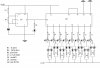
On a breadboard i succeeded in making a circuit with a 555 chip and a 4017 chip because I would like the first word (four-lettered, about 80 leds) to flash as a whole and the second word (8 letters of about 20 leds each) to flash sequentially. I power it with a wall-mart. I placed one led to represent the first word, out of the 555, and 8 leds to represents the letters of the second word, and it flashes nicely. :)
Now I am stuck because I need to amplify the power out of the ics, I think. I tried to place a 2n2222 transistor out of one of the pins of the 4017, with a 1.5 k resistor before and replaced the led with a flash light bulb rated 500 mAmps (I don´t want to test it directly on my sign and risk losing hours of soldering work) but it does not light up. :confused:
the I left the transistor in place and put back the led instead of the bulb and it flashes.
I imagine I need 500 mAmps for each letter, and about 1.6 Amp for the first word, but I cannot figure what transistor to use.
Maybe I can connect the load directly to the power source and then power the circuit with a battery ? Is that possible ?
I would be very thankful for some help
 
oops, sorry I must have meant a wall-wart, for me it is a transformer of ac to dc,you can graduate it at 1,5 V, 3V, 4,5V, etc, but I measured with a voltmeter and graduated at 4,5V it delivers 6,42 V which is what I use since I read somewhere than more voltage could damage the 4017 ic.
Sorry for the mistake, English is not my language.:eek:


4017 can handle I believe up to 15v (might be 18v but don't remember exactly), so you are at a very safe level and have room to increase.
 
What is the current rating of your wall-wart? Some of those multi-voltage wall-warts are very low power.

The 2n2222 transistor is only good for 500mA, for higher current you may be better using a cheap power mosfet such as an irf510.
 
I don´t understand your question. I can graduate it to deliver more volts, and don´t know about the Amps because whan I tried to measure it with my voltmeter, it says OL.
I have kept on experimenting and when I changed the 2n2222 for a 2n4401, I obtained a flicker from the flash light. Youpi!!!:p
So, I think I could manage to light the letters of the second word, but I still have a problem with the first word, that I want to light all together.
It sums about 85 3V leds
Can I try a Darlington pair? if yes, are they all the same or need I buy one specific?

Also, I am surprised, because the led representing that word on my breadboard flashes with every sequential flash out of the 4017, and I thought it would flash once for every cycle as I thought the 4017 was a divider. The single led is connected to pin 3 of the 555. As I said i´m a complete beginner but the googling I have been doing gave me the idea the current went to the 4017 to flash the sequence, and then to the other led connected to the 555 if there is one, as it happened when I made an alternate flasher with the 555 first to start with something simpler.
 
The 2n2222 transistor is only good for 500mA, for higher current you may be better using a cheap power mosfet such as an irf510.[/QUOTE]

thank you, I have no idea what you mean but it´s a clue I will investigate.
 
4017 can handle I believe up to 15v (might be 18v but don't remember exactly), so you are at a very safe level and have room to increase.
Thank you, then I will risk increase the wall-wart at 6V (it actually delivers then 8,52V)
 
You didn't attach a schematic so I don't know how you connected the transistor.

If you overload the wall-wart (of course its max allowed current will be marked on it) then it will get hot and might catch on fire or burn out. Its voltage drops low when it is overloaded.

A CD4017 has a typical output current of only 1mA to 8mA when its supply voltage is 8V.
A 500mA incandescent light bulb needs 5A to begin turning on when it is cool.
A 2N2222 or 2N4401 will have an output current of only about 100mA and a loss of voltage with the very low base current.
 
You didn't attach a schematic so I don't know how you connected the transistor.

Here, I just made a diagram of what is on my breadboard
I tried to attach it.
Doing this, I realised i haven´t made the connection between pin 4 of the 555 ic and the supply line, and though, it works.:confused:
(the 555 is very forgiving, I must say)
If you are as kind as to look at it and tell me if it´s okay ?
I still have to find a transistor for the leds i will connect between pin 3 and 1 of the 555 ic. I´m thinking of testing the tip31c.
Changing the single leds for the bulbs out of the 4017, I made a change because before, the positive lead of the led was connected to the ic and the negative lead to ground through a 330 ohm resistor.
(I painfully gropple my way in this new world of electronics, and here in Costa Rica, there is no way to have any help from the vendors in electronics stores)


If you overload the wall-wart (of course its max allowed current will be marked on it) then it will get hot and might catch on fire or burn out. Its voltage drops low when it is overloaded.
I looked at my wall-wart and it reads "ac-dc adaptor universal, current: 1000 mA MAX (made in China)" (why doesn´t it says 1A instead of 1000 mA, I can´t figure, I think it´s the same, no?)
So, do you think there is a risk I might provoke a fire?

Because, whan I tried lighting all the leds together of the first word of the display sign to test the soldering work, I powered it with that wall- wart and it worked just fine, but I rather have the word flashing for two reasons: it is more eye-catching, and the leds being in a foam board, i don´t want them to be lit continuously, for the risk of catching fire.
Thank you so much
 

Attachments

  • diagram display sign.jpg
    diagram display sign.jpg
    1.1 MB · Views: 464
Last edited:
Resistors are not needed from the outputs of the CD4017 to the bases of the power transistors because the output current of the CD4017 is only 5mA when its supply is only 6V.
But the TIP31 power transistors need a base current of 25mA to 50mA to properly turn on 500mA light bulbs. TIP120 power darlington transistors or logic-level Mosfets would work. The darlington will cause a voltage loss to the light bulb of from 0.75V to 1.2V. The darlingtons also do not need resistors from the outputs of the CD4017 to their bases.

The CD4017 turns on only 1 output at a time. So the average current is a little more than 500mA and your 1A wall-wart will be warm but not hot.
 
thanks

thank you so much for your enlightened advice (no pun intended)
I used the light bulbs as a test but the final project is made only of leds
and I´m thinking of the tip31 for the alternate flasher out of the 555ic: I read somewhere that this ic has an untypical output of 200mA, so do you think the tip31 might work?
it is more powerful than a 2n4401, right?
Also, it is intended to light up 85 leds, which sum up more than 1000 mA. I never considered that angle doing my project, because as I said, when I tested the soldering work of the 85 leds with the wall-wart, it worked just fine for me.

Between the 4017 outputs and the 2n4401 transistors I can then omit the resistors ? Don´t I have to put even a 1ohm resistor to be on the safe side ?

Also, I keep on being puzzled by the fact that the led representing the 85 leds (out of the 555ic) on my breadboard flashes with every sequential flash out of the 4017, and I thought it would flash once for every cycle as I thought the 4017 was a divider. I got the idea the current went to the 4017 to flash the sequence, and then to the other led connected to the 555 if there is one, as it happens in the case of an alternate 555ic flasher.
Anybody can explain that to me?
Thank you
 
The output current of the CD4017 is only about 5mA when the supply is only 6V.
The current is so low that a series resistor is not needed to drive anything.
But the TIP31 transistor needs a base current of 50mA to 100mA to properly turn on a 1000mA load.

Didn't you read where I said that TIP120 darlington transistors will work instead of TIP31 transistors?

The output of the 555 can supply up to 200mA. Then a current-limiting resistor can be between the outrput of the 555 and the base of a TIP120 darlington transistor because if the 555 drives the base of a TIP31 transistor with 100mA then the output high voltage of the 555 might not be high enough to clock the CD4017.

Each time the output of the 555 goes high then the CD4017 sequences to its next output.

I think your total load current will be more than the current from your wall-wart supply.
 
what if?

thank you audioguru
Then I will try to find another power supply
with a higher max current.

Also I´m thinking that maybe I could change the circuit
and put a relay first, to get the alternate flashing of the first and second word.
After the relay, for the first word (85 leds) I imagine I would still need a power transistor (I need to investigate the output of the relay, then, if I understood something of your explanations) and for the second word of eight letters I would use this circuit of 555 and 4017, with no resistors at the base of the transistors.
Thus, I don´t use the 555 as an alternate flasher but only to drive the 4017.

Does it seem a good idea ? Is it feasible ?
 
I would use two darlington transistors and a transistor instead of a relay.

How much current does each transistor (driven from the CD4017) drive?
A TIP31 transistor with a base current from the CD4017 of only 5ma will have an output of only 50mA to 100mA.
 
At the moment, on the breadboard,
the output pins of the 4017 are connected to 2n4401 transistors
to flash sequentially each group of leds representing the letters of the second word, and it works. Each letter sums 20 leds on average, of 20mAmps each, thus about 400 mAmps.
My problem is for the first word, that I want to flash alternately (and all the leds together) with the second and which sums 72 leds in parallell with 330 ohm resistors each.
Since I cannot get the 555 to blink a led (on the breadboard, representing the first word) only once between each 4017 sequence, I thought that i could either connect the first word to another 555ic, or I could place a relay, which I understand can drive higher currents. So I thought that maybe the relay with just a transistor can light up the 72 leds of the first word, and then send the current to the 555 and 4017 to light sequentially the second word, which is the effect I try (painfully) to attain.
You seem not very keen on relays, are they problematic ?
If I use two darlington pairs, (one connected to the other?) it would be out of the 555? Would I then get the alternate flashing of the two groups ?
I am sorry that English is not my language and surely my explanations are a little confused.
 
The 555 can drive one darlington transistor that flashes one group of LEDs.
The 555 can drive a transistor (used as an inverter) that drives a second group of LEDs. Then the groups alternate their flashing.

Maybe the first darlington can drive the second darlington and the first darlington drives the first group of LEDs and is the inverter.
 
project completed!

dear audioguru,

I have been silent a long time for lack of time
but I finally completed my project and built an aluminium and plexiglass frame to encase the sign (the circuit, I placed in a small polystyrène case to support the movements, because I have to hang the sign each morning and take it off each night, for fear of robbery since it is the ONLY sign this style in the whole city.) I am very happy with the result, especially since I started with zero knowledge in electronics. The first group of leds forming the first word blinks rapidly and the tip31c was too powerful in fact since they are ultrabright leds and it could harm the sight, so I settled for a 2n2222.
So every day I wait for the crepuscule, and contemplate the reflects of my display sign on the opposite side of the street. I would have posted a photo but my software iPhoto does not work anymore since I updated to Leopard.

I thank you very much for your help that meant a lot to me: Actually you are the only person who helped me in this project and it meant a lot because I had my moments of doubt. I must confess that now I have tasted leds my mind sometimes wanders to other invents to illuminate daily life...
I will let you know if I launch in another led project.
Thank you for sharing your knowledge, it is such a precious thing.
 
sony tv circuit diagram

I am looking for A sony TV circuit diagram for model KV-G21P2S.
Looking forward kind help.Thankyou in advance.

Regards,
tkaru
 
I am looking for A sony TV circuit diagram for model KV-G21P2S.
Looking forward kind help.Thankyou in advance.

Regards,
tkaru
Please start your own thread instead of hyjacking this thread.
 
Status
Not open for further replies.

Latest threads

New Articles From Microcontroller Tips

Back
Top