Continue to Site

Welcome to our site!

Electro Tech is an online community (with over 170,000 members) who enjoy talking about and building electronic circuits, projects and gadgets. To participate you need to register. Registration is free. Click here to register now.

  • Welcome to our site! Electro Tech is an online community (with over 170,000 members) who enjoy talking about and building electronic circuits, projects and gadgets. To participate you need to register. Registration is free. Click here to register now.

230 Volts LED night light project

Status
Not open for further replies.

RODALCO

Well-Known Member
230 Volts LED night light project.

Here is an addition to the popular LED indicator lights.

I have made some LED lamps as well for 230 Volts. I used an old base from a discarded compact fluorescent lamp. It got the B22 socket and has a wider base which is excellent for the LED project. I use them as night lights in my house so I don’t have to switch lights on and wake myself up too much when going to the loo.

Of course an Edison E27 base can be used as well and for 110 Volts use 2 *8k2 or 10 k Ohms resistors in series.

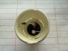
3552 The B 22 base with 4 * 8k2 ohms , 1 Watt resistors and the 1 N4007 diode.

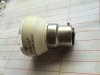
3553 Side view of B 22 base.

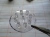
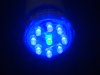
3554 9 LED’s glued with araldite to a transparant pvc base. (8 blue, 1 green).

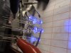
3559 Section of LED’s under test. I find it very handy to test for correct polarity when a string of LED’s is soldered. It saves a lot of messing about later on when things don’t work when a LED is put in the wrong way around. I use a 12 Volt power supply limited to 10 mA, so I can’t blow up any LED’s.

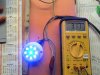
3561 Test run at 230 Volts. Current is only 3.17 mA.

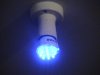
3565 LED lamp going in my lounge.

3566 LED lamp from different angle.

Regards, Raymond

Keen to hear ideas or see photo’s from other forum members who have built some LED lamps.
 

Attachments

  • DSC03552.JPG
    DSC03552.JPG
    112.1 KB · Views: 1,621
  • DSC03553.JPG
    DSC03553.JPG
    111.3 KB · Views: 1,120
  • DSC03554.JPG
    DSC03554.JPG
    119.2 KB · Views: 1,175
  • DSC03559.JPG
    DSC03559.JPG
    125 KB · Views: 1,178
  • DSC03561.JPG
    DSC03561.JPG
    151.8 KB · Views: 1,125
  • DSC03565.JPG
    DSC03565.JPG
    119.3 KB · Views: 1,035
  • DSC03566.JPG
    DSC03566.JPG
    113.9 KB · Views: 1,105
Why use blue, it destroys your night vision?

Use red because the rods don't respond to it which enables you to stay dark adapted.
 
Thanks for the tip Hero999. I like blue that's why it choose it.

You got a good point there, thanks.

Any colour led may be used, it's up to the user.
 
good to see u back in LED action "RODALCO"
and thanks for the details.

during these days i come across some data where they said one can drive the LED much brighter using PWM method.
say 20ma is the suitable current for LED,if we drive them at 50ma it will generate more brightness along with lot of heat eventually it will burn out.
in PWM mode the current will keep switching.giving the time for LED to cool down.
have u done any research over this LED driving method.
i know iam going from 220v AC to PWM dc(off topic),but its related to to LED
 
Driving an LED past peak IsubF works just fine; you need only ensure the average delivered power doesn't exceed the maximum rated power dissipation of the device over a very short period of time. Note that overdriving an LED in this manner will likely cause its peak wavelength emission to shift up slightly. This characteristic has been employed deliberately, for example to get blue LEDs to emit in the UV.
 
The PWM thing only works on some red and infrared LEDs, modern blue LEDs actually tend to be more efficient at lower currents.

The UV trick only works on a specific kind of blue LED that's no longer made.
 
A 555 timer PWM dimmer isn't really compatable with this kind of power supply as it is at the moment. To make it work with a 555 you need to add a zener diode and a filter capacitor to give a stable DC power supply.

I wouldn't bother as I don't see the point in PWM unless you do want to change the brightness.
 
why iam running behind this PWM-over driving led is,
i saw a product made by the local company in my area.they make LED lights.they are so bright and nice that i amazed.i did some inquiry abt that product.and came to know that they are using same LED's that iam using for my experiments.my friend,(who work in that company) said that they are using some sort of driving circuit(involving flat heat sinks) to avoid the more number of LEDs to get more brightness.
then i had this PWM'ing in my mind.
 
Hero999 said:
The PWM thing only works on some red and infrared LEDsV trick only works on a specific kind of blue LED that's no longer made.
Not quite true. Nearly any LED can be driven to a higher luminance than designed for by PWM overdriving; although, as you noted, the efficiency may suffer as a result. Whether the increase in light output is visually noticeable or not depends on the LED and its emitted spectrum. And all LEDs exhibit some degree of spectral shift when driven at other than nominal current (both under- and over-driving). Whether the shift is towards the blue or red depends not only on the relative magnitude of the driving current, but also on the specific chemistry. Many LEDs will blueshift when overdriven, but some will redshift instead. There isn't much need anymore to drive a blue LED to emit UV, what with the ready availability of UV LEDs with peak emissions as low as 360 nm (and even lower if you're willing to pay for it.) If you can manage to wade through the technical jargon, the following article addresses the spectrum shift issue:

https://www.electro-tech-online.com/custompdfs/2008/03/Gu-SPIE6337-17.pdf
 
I'm not disputing that LEDs will give more light when pulsed at higher currents. It's just not worth if because the efficiency invariably suffers and the response of the human eye acts like a low pass filter so it won't make any difference to the overall brightness. For example PWMing an LED at 50% duty cycle with double the current might make it twice as bright but it won't look any brighter.

PWMing is only worth it if the LED does work better at higher currents or it is used for transmitting information as the range may more than double without using any extra power.
 
I agree with Hero.
My Ultrabright LED chaser projects use PWM to dim the LEDs. When the duty-cyle is 20% and less then the LEDs are dimmed. When the duty-cycle is 1/1000 then they are very dim. The peak current is exactly as high as when they are bright.
 
audioguru said:
The peak current is exactly as high as when they are bright.
Uh, yes, it would be. PWM doesn't change the applied voltage during the "on" time and therefor doesn't affect the current draw.
 
Horrible for colour rendition.
 
Ive done several White LED lamp conversions so far. I use a capacitive coupler type drive circuit. That theoreticaly only uses the power that the actual LEDs take so there is no resistor power loss.

I posted a basic schematic on another LED related thread. That circuit works great! Never had one fail yet. But from long term running tests I have found most of the new 100k hour rated LEDS get very dim after a year or two!
The old reds, greens, and yellows seem to run for years with no dimming when compared to unused ones from that batch.
The newer stuff oddly does start to show a noticeable dimming after a few months doing this comparison test.

And no I did not use the cheap chinese LEDs!
 
Last edited:
It's probably the phosphor ageing.
 
LED's at 5 mA

I find that most LED's give already an excellent light output at 5 mA.

Most people are obsessed running them at 20 mA's or more, which will cause the LED to loose light output or fail prematurely.
It also requires a bigger series resistor.

I have experimented with capacitors too, although I have found that the inrush current needs to be limited via a 2k2 1 or 2 Watt resistor at least, to avoid spikeing the LED.
47 to 220 nF to get between 5 and 20 mA's, bear in mind that you need at least 400 Volts rated caps !!

For simple night lights around the home this concept works well.

I put a clip on You Tube which shows the difference in running current between the series diode 1N4007 and the LED's.

I will add the link soon.

RF.
 
Link to YouTube

YouTube - 230 Volts LED and schema

This shows you the reduction in current drawn from the mains.

I have a couple of other LED clips under my RODALCO2007 username there as well for you to watch.

enjoy !!

RF.
 
Status
Not open for further replies.

Latest threads

New Articles From Microcontroller Tips

Back
Top