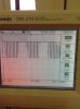
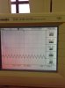
I see. Thanks MrAI. With the triangular waveform, I input to another comparator on the non-inverting input and a sine wave on the inverting input. It should have a PWM output but the waveform seems distorted. Do you have any idea on why?
Hi again,
Yes. Your input sine wave operates around a different bias point than the output triangle from the op amp. In an ideal circuit built like that the output triangle does not go from zero to +Vcc, it goes from Vcc/4 to 3*Vcc/4 and is centered around Vcc/2. Now if the sine goes from some negative peak to some positive peak then you'll only see PWM during the time when the sine is between Vcc/4 and 3*Vcc/4, and the rest of the time the output will either be high or low.
So to get it to work better you'll have to add an offset to the sine wave to get it to reside between the two levels above. With a 5v power supply that means the triangle ramps between 1.25v and 3.75v (ideal circuit) so the sine wave levels would all have to be within that range.
That's for an ideal circuit with exact values and perfect rail to rail op amps. For the LM324 for example the output does not reach all the way to +Vcc so it causes the triangle to run between somewhat different levels. So it might be best to measure those levels and then determine what is best for the sine wave. The sine wave will need a DC offset and also limited amplitude. We can calculate those requirements or you can measure the triangle.
Note however that with an imperfect op amp like that the triangle will not be symmetrical either. It's ramp up time could be quite different from it's ramp down time. That may or may not bother your output PWM signal. For a more symmetrical triangle use a rail to rail op amp or we'll have to do some calculations to see what we can adjust to get it right with the cheaper op amps.
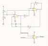
One more note, since C=5uf (approximate) and R1=1k, the output triangle frequency is approximately:
f=1/(2*R1*C)=1/0.010=100Hz. This means your sine wave will have to be around 5Hz if you want to see 10 pulses per half cycle. If you use a faster triangle you can use a higher frequency sine wave, but you'll have to stay within the operating range of the op amp.
Also, if you use a power supply voltage which is higher than 5v (like 10v) you'll see a more symmetrical triangle even with the cheaper op amp assuming you still stay within the operating range of the op amp. The slew rate determines the fastest ramp of the output, but the second part (the comparator used for the triangle) is expected to have a clean rise and fall time which means it has to have a comparable faster slew rate. If the slew rate is too low for that section, the output triangle will look like a partly exponential wave rather than a triangle because R1 will end up getting a current through it that varies during the triangle wave slopes instead of a constant current.
")