Hi, just to check, to determine the max output frequency of the comparator, Fout = 1/[Vp/SR], then for TL072, I figure that the max freq will be around 416kHz. Did I made a mistake somewhere?
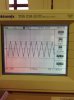
I realised that, by decreasing the value of the capacitor, the voltage spikes and inconsistent in the amplitude seems to be worse. So like what you said in the previous post, I should find a value of R and C suitable that will not affect the waveform?
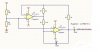
And is there any mistakes in my schematic? I had made the necessary adjustment for the resistors and capacitor.
Hello,
Yes there is a major mistake now because apparently you went from a single supply to a dual plus and minus supply. Before because of the connections of Ra and Rb it was assumed that the circuit was to operate from a single positive supply. Now it is shown operating from plus and minus 10 volts so we will now change that assumption.
Using a plus and minus supply means the junction of Ra and Rb (the reference voltage) must be zero. That means you either need to connect the bottom of Rb to ground, or eliminate Ra and Rb altogether and just connect that junction to ground which is zero volts.
Next, the formula for the output frequency for an ideal circuit is:
F=1/(2*R1*C1)
but you have it written as:
F=1/2*R1*C1
which is not the right way to write it out and might cause confusion because that means the same as:
F=(1/2)*R1*C1
which as you can see is definitely not the same. So we write it with parens as:
F=1/(2*R1*C1)
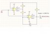
Next, if you calculate your output frequency with the values you have shown in that new schematic it looks like your frequency now will be close to 1MHz. That's probably too high, so you should start with a much lower frequency to start with. You can always easily try to raise it later.
Starting with R1=1000 and C1=5uf, or even R1=2k and C1=2.5uf, we get a frequency that is nice and low to start with:
F=100Hz
and the total period is:
Tp=2*R1*C1
and so half of the total period is:
Thp=R1*C1
and so one quarter of the total period is:
Tqp=R1*C1/2=Tp/4
and with R1=1k and C1=5uf we get a Tp of:
Tp=0.01 seconds
so Tp/4 is simply:
Tqp=Tp/4=0.0025 seconds
so now we have Tqp. Next we'll calculate the output of the op amp when the comparator upper threshold is reached. This comes from a simple observation that when the output of the comparator is low and the comparator threshold is reached, the unsigned current through R3 is:
iR3=Vm/R3
where Vm is the unsigned negative output characteristic of the op amp.
The negative output characteristic of the op amp is the lowest output the comparator can put out given the negative power supply level. This can be quite different than the actual power supply voltage. For example, for a TL072 with a minus 10 volts power supply the output may only reach down as far as -7 volts, not -10 volts. It may be better than that -7 volts, but lets assume -7 volts for now.
With minus 7 volts on the output, that means we have an unsigned current:
iR3=7/R3=7/4000 amps.
To get the comparator threshold to equal zero volts, this means we must have an op amp output of:
Vout=iR3*R2=7/4000*2000=7/2=3.5 volts.
So the output of the op amp will be 3.5 volts when the comparator threshold is reached. This means the triangle slews from -3.5v to +3.5v, then back down to -3.5v, so one quarter of that means it slews from 0 to 3.5v. Knowing this and the quarter period Tqp, we can calculate the slew rate of the triangle itself:
TriSlew=3.5v/Tqp
which comes out to 1400 v/sec (volts per second), which is also equal to 0.0014 v/us (volts per microsecond), or 1.4v/ms (volts per millisecond). To comply with the rule of thumb that we want the comparator at least 10 times faster than that, we need a comparator who's output can slew at a rate of at least 0.014 v/us or 14v/ms. Since it has to slew from -7v to +7v that means we need a rise (and fall) time of at least 1ms. That shouldnt be hard to find.
MORE ABOUT THE COMPARATOR OUTPUT CHARACTERISTIC
As mentioned above, if the TL072 is used as the comparator then the output will not reach up to either rail of the power supply. From the data sheet we find that it can be anywhere from Vcc-1.5 to as low as Vcc-3 for the positive excursion, and from -Vcc+1.5 to -Vcc+3 for the negative excursion.
This is typical for op amps but some are not as symmetrical as that either, and it is also questionable if both positive and negative excursions will match closely on any op amp. Mismatched positive and negative excursions will cause non symmetry in the triangle, which may or may not be objectionable to the application, but can be readjusted by changing the reference voltage to be right at the center of the two excursions:
Vref=(Vp+Vm)/2
So for Vp=+7 and Vm=-7 we get:
Vref=(7+(-7))/2=0 volts
but for Vp=+7 and Vm=-6 we get:
Vref=(7+(-6)/2=0.5 volts
Resistors Ra and Rb would be adjusted to obtain this value.
For PWM though almost any triangle will usually work, even a sawtooth, as long as the application is tested carefully over the full operating range for stability because the dynamics when there is feedback involved can change due to the time shifting nature of the PWM generated with a sawtooth versus PWM generated with a symmetrical triangle...it could be better or worse depending on the shape of the sawtooth.