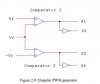
Get rid of C2 because the inputs of the comparator must have a DC reference voltage that is 0V. The sine-wave must also be DC-coupled.
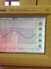
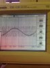
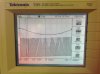
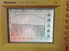
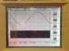
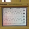
I think the amplitude of your sinewave is too high and causes the TL082 comparator to have "opamp phase inversion" when the sinewave voltage gets within 4V from the negative supply. I do not know why the amplitude from the comparator is so low, it is about half the 17V p-p level it should be.
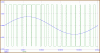
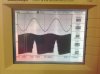
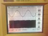
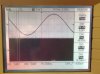
Since the total supply for the integrator is only 10V then the triangle wave is only about 8.5V peak-to-peak. Then the sinewave must be attenuated so it is also 8V peak-to-peak or whatever the triangle is.
I think the amplitude of your sinewave is too high and causes the TL082 comparator to have "opamp phase inversion" when the sinewave voltage gets within 4V from the negative supply. I do not know why the amplitude from the comparator is so low, it is about half the 17V p-p level it should be.
Since the total supply for the integrator is only 10V then the triangle wave is only about 8.5V peak-to-peak. Then the sinewave must be attenuated so it is also 8V peak-to-peak or whatever the triangle is.