Continue to Site

Welcome to our site!

Electro Tech is an online community (with over 170,000 members) who enjoy talking about and building electronic circuits, projects and gadgets. To participate you need to register. Registration is free. Click here to register now.

  • Welcome to our site! Electro Tech is an online community (with over 170,000 members) who enjoy talking about and building electronic circuits, projects and gadgets. To participate you need to register. Registration is free. Click here to register now.

2 stage common emmiter with feedback

Status
Not open for further replies.

waverunner

New Member
hello guys,
I would like to explain me how the feedback(R11,c2) affects the amplifier. I know about feedback from collector, but not from emmiter.
Thanks a lot
 

Attachments

  • Untitled.jpg
    Untitled.jpg
    35.4 KB · Views: 656
The emitter of the second transistor has exactly the same signal as its base which has exactly the same signal as the collector of the first transistor.

So R11 and C2 provide negative feedback.
But it is applied to the input which reduces the input impedance that was already low without the negative feedback.
 
It is like an inverting opamp except its open-loop gain is only about 100 instead of 100,000 like an opamp. So the gain is a little less than R11/R1 (10k/150= 67) so the gain is about 50, except the 1k load on the 6.8k collector resistor of the second transistor reduces the gain to about 7.3.

I have the formula on my hard drive but I can't find it.
 
I design the circuit in spice, and the voltage gain is 15,97... now i want to confirm that.

It only matters in school because the input impedance is so low that the circuit is not practical. The gain might be only 16 if the source impedance is zero. If the source impedance is more than zero then the circuit attenuates it and the gain is less.
 
I design the circuit in spice, and the voltage gain is 15,97... now i want to confirm that.


Hi there,


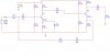
The input voltage is divided by 150 which puts some current into
the base of Q1, and that amplifies that a lot because of C4 so
the output at the collector WOULD be very large, except that that
signal is coupled to Q2 and Q2's emitter feeds the feedback network
R11 and C2 and so the gain of Q1 is reduced to about 10000/150
which is around 67. Unfortunately, it looks like Q2 is not set up
right to match the output impedance (1k) so that output impedance
causes a lot of attenuation. With a slight gain of very roughly 2
for Q2 and the attenuation of 7k to 1k the output gain would be
very roughly 19. The very low output impedance and Q2 bias
probably not in the best place you may also see quite a bit of
clipping of the output signal so you probably get a lot of distortion.
With a better circuit for Q2 you can probably do a lot better.
 
Last edited:
Status
Not open for further replies.

Latest threads

New Articles From Microcontroller Tips

Back
Top