Electro Tech is an online community (with over 170,000 members) who enjoy talking about and building electronic circuits, projects and gadgets. To participate you need to register. Registration is free. Click here to register now.
Welcome to our site! Electro Tech is an online community (with over 170,000 members) who enjoy talking about and building electronic circuits, projects and gadgets. To participate you need to register. Registration is free. Click here to register now.
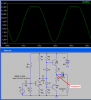
sorry!!the capacitro c2.i deleted it and the o/p was k.what i dont understand is why the filter made by c2 and the r5parallelr6 distorting the o/p?have i miscalculated the value of the capacitor??sorry agaian!!!
sorry!!the capacitro c2.i deleted it and the o/p was k.what i dont understand is why the filter made by c2 and the r5parallelr6 distorting the o/p?have i miscalculated the value of the capacitor??sorry agaian!!!
The problem is with your emitter follower, Q2. You have attempted to bias the emitter at approx. half the supply voltage, but the 8 ohm resistor nearly shorts the emitter to ground. This also drags down the base voltage, because your base bias network cannot supply enough current to keep the base voltage up, and it lowers the input impedance for the positive half of your waveform, causing the distortion you see on the Q1 collector when C2 is in place. Delete the 8 ohm resistor and see what happens.
As I said before, it is not a good idea to drive a speaker with DC.
I've modified your circuit so it drives an 8hm: speaker with no problem.
The forum wouldn't let me attach the .asc file so I've enclosed it in code tags. Just paste it into a text editor such as notepad of emacs, save it as a .asc file and open it in LTSpice.
Code:
Version 4
SHEET 1 880 680
WIRE 304 -240 -336 -240
WIRE -448 -192 -592 -192
WIRE -336 -192 -336 -240
WIRE -336 -192 -448 -192
WIRE -144 -192 -336 -192
WIRE -16 -192 -144 -192
WIRE -448 -176 -448 -192
WIRE -592 -144 -592 -192
WIRE -16 -144 -16 -192
WIRE 304 -112 304 -240
WIRE -144 -96 -144 -112
WIRE -80 -96 -144 -96
WIRE -144 -32 -144 -96
WIRE -16 -32 -16 -48
WIRE -448 48 -448 -96
WIRE -368 48 -448 48
WIRE -144 48 -144 32
WIRE -144 48 -304 48
WIRE -16 64 -16 48
WIRE 48 64 -16 64
WIRE 144 64 112 64
WIRE -144 80 -144 48
WIRE -16 80 -16 64
WIRE -448 96 -448 48
WIRE -784 144 -944 144
WIRE -592 144 -592 -64
WIRE -592 144 -720 144
WIRE -512 144 -592 144
WIRE -592 192 -592 144
WIRE -144 208 -144 144
WIRE -80 208 -144 208
WIRE 144 208 144 64
WIRE -944 224 -944 144
WIRE -448 224 -448 192
WIRE -144 224 -144 208
WIRE -944 336 -944 304
WIRE -592 336 -592 272
WIRE -592 336 -944 336
WIRE -512 336 -592 336
WIRE -448 336 -448 304
WIRE -448 336 -512 336
WIRE -352 336 -448 336
WIRE -144 336 -144 304
WIRE -144 336 -352 336
WIRE -16 336 -16 256
WIRE -16 336 -144 336
WIRE 144 336 144 288
WIRE 144 336 -16 336
WIRE -512 352 -512 336
WIRE -352 400 -352 336
WIRE 304 400 304 -32
WIRE 304 400 -352 400
FLAG -512 352 0
SYMBOL npn3 -512 96 R0
SYMATTR InstName Q1
SYMBOL res -608 -160 R0
SYMATTR InstName R1
SYMATTR Value 10k
SYMBOL res -608 176 R0
SYMATTR InstName R2
SYMATTR Value 1k
SYMBOL res -464 208 R0
SYMATTR InstName R3
SYMATTR Value 100
SYMBOL Misc\\signal -944 208 R0
WINDOW 123 0 0 Left 0
WINDOW 39 0 0 Left 0
SYMATTR InstName V2
SYMATTR Value SINE(0 .5 400)
SYMBOL res -464 -192 R0
SYMATTR InstName R4
SYMATTR Value 1k
SYMBOL res -160 -208 R0
SYMATTR InstName R5
SYMATTR Value 1k
SYMBOL res -160 208 R0
SYMATTR InstName R6
SYMATTR Value 1k
SYMBOL npn -80 -144 R0
SYMATTR InstName Q2
SYMBOL Misc\\battery 304 -128 R0
WINDOW 123 0 0 Left 0
WINDOW 39 0 0 Left 0
SYMATTR InstName V1
SYMATTR Value 20
SYMBOL res 128 192 R0
SYMATTR InstName Speaker
SYMATTR Value 8
SYMBOL cap -304 32 R90
WINDOW 0 0 32 VBottom 0
WINDOW 3 32 32 VTop 0
SYMATTR InstName C2
SYMATTR Value 10µ
SYMBOL pnp -80 256 M180
SYMATTR InstName Q3
SYMBOL diode -160 -32 R0
WINDOW 0 39 32 Left 0
WINDOW 3 -28 29 Left 0
SYMATTR InstName D1
SYMBOL diode -160 80 R0
WINDOW 0 42 30 Left 0
WINDOW 3 -29 30 Left 0
SYMATTR InstName D2
SYMBOL res -32 -48 R0
SYMATTR InstName R7
SYMATTR Value 1
SYMBOL res -32 64 R0
SYMATTR InstName R8
SYMATTR Value 1
SYMBOL Misc\\EuropeanPolcap 48 80 R270
WINDOW 0 32 32 VTop 0
WINDOW 3 0 32 VBottom 0
SYMATTR InstName C3
SYMATTR Value 1000µ
SYMBOL cap -720 128 R90
WINDOW 0 0 32 VBottom 0
WINDOW 3 32 32 VTop 0
SYMATTR InstName C1
SYMATTR Value 10µ
TEXT -752 -32 Left 0 !.tran 0 5 1 1
That's weird. .ASC is listed as a valid attachment type, and I have attached them with no problem.
Disclaimer: I am not an audio guru.
You can drive a speaker with that, but the gain is low and I think the distortion will be high if you want enough power to actually hear it.
I tried adding negative feedback around the entire circuit and many other things but the output transistors do not have enough OOMPH.
I cannot make an attachement because it say that I have exceeded my attachments quota!!!!!
Again. Last time i deleted all my attachments then admin removed the quota. Now the quota is back!
well thanks roff making a power amplifier for running my 8ohm speaker was my seond task.i am practising making amplifier and different types of circuits.any hints??
I tried adding negative feedback around the entire circuit and many other things but the output transistors do not have enough OOMPH.
I cannot make an attachement because it say that I have exceeded my attachments quota!!!!!
Again. Last time i deleted all my attachments then admin removed the quota. Now the quota is back!
Before you get carried away (like some have already!), PM Electromaster and tell him, presumably it's the default setting on the last software upgrade.
I tried adding negative feedback around the entire circuit and many other things but the output transistors do not have enough OOMPH.
OOMPH?? and if you dont mind me asking why we dont use a class c or d amplifier because i have seen most of the people make clas ab amps as power amplifiers.AND from where can i learn about class c and d amps?
OOMPH is power.
The output transistors in the class-AB circuit don't have enough base current to drive an 8 ohm speaker properly.
Electromaster fixed the software bug that caused the temporary attachment quota problem.
Class C is used in radio circuits where an LC tuned circuit removes the harmonics that are caused. Class-C would cause severe distortion (lots of harmonics) in an audio amplifier.
Class-D amplifiers have a very complicated high frequency pulse-width-modulation switching circuit.
There are sites that host your schematics and pictures. Some of them have horrible pop-up ads. Some of them take forever to wake up.
Here's a slightly improved version, it's not perfect or efficient but it has lower bias resistors for more power and negative feedback (provided by R1 to R3) to remove the distortion.
Hi Eric,
Thanks but no thanks.
The article is for mathamaticians who are designing ICs. I haven't used math for many years and I have never designed an IC.
I designed audio filters with opamps. I worked with products with DSP ICs that had programmed filters.
That's what negative feedback does for you but at least it will drive the speaker, there's no distortion and you need to add a pre-amplifier to make this circuit useful.
You could make Q1 a darlington and R1 1M if you want more gain.
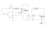
i have just downloaded the file couldnt get online all this time.listen here is a different transistor switch i found something like this in the forum.for the one on the left it was said that the led wud light if the base was driven low and for the right it was said that it would light when the base was driven high.i have measured the voltage and the currents as seen in the picture also can you tell me how its working.i understand the first one because npn sinks current correct me if i am wrong? and what is thje reason for the humangous current in the right hand side circuit??
No. The LED and the transistor would burn out as shown without a current-limiting resistor. The 10k resistor applies base current to the transistor to turn it on. Then the base is about +0.7V. If you connect the base to 0V then the transistor will turn off.
for the right it was said that it would light when the base was driven high.
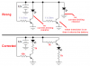
You had the LED connected directly across the battery so it would burn out instantly. You had the transistor connected so that it shorts the battery and burns out.
My corrected circuit shows a current-limiting resistor in series with the LEDs.
The circuit on the right has the transistor connected as an emitter-follower so that its emitter is about +11V as shown and if the base is connected to 0V then the transistor turns off.
Did you notice that on my schematic there are no wires running all over the place and no wires cross?
This site uses cookies to help personalise content, tailor your experience and to keep you logged in if you register.
By continuing to use this site, you are consenting to our use of cookies.