Continue to Site

Welcome to our site!

Electro Tech is an online community (with over 170,000 members) who enjoy talking about and building electronic circuits, projects and gadgets. To participate you need to register. Registration is free. Click here to register now.

  • Welcome to our site! Electro Tech is an online community (with over 170,000 members) who enjoy talking about and building electronic circuits, projects and gadgets. To participate you need to register. Registration is free. Click here to register now.

2 stage BJT amplifier

Status
Not open for further replies.

patroclus

New Member
Hello again,

I just built and tested my first 2 stage BJT amplifier.
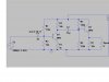
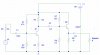
I'm using it to drive a small 8 ohm speaker. For these reason, I used an emitter follower as output stage, and a common emitter as first stage. But I would like to do it better now.
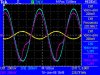
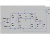
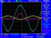
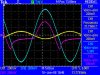
Here is the circuit, and the waveforms (CA coupling). Yellow is the input signal. Blue is Q1 output. Magenta, the speaker's voltage.

The first thing I see wrong is the strange clipped output waveform, which I suppose is due to the grounded speaker terminal. I think voltage can't drop below 0 V because there's no negative power source in the circuit, but in the second waveform image I used a 10 timer higher frequency, and the output gets closer to a sine wave, and aparently going below 0 V (but I'm not 100% sure about this because I forgot to check it in CC coupling mode). Also it gets bigger in amplitude, and don't really know why, as the 220 uF capacitor should be high enough to let the low frequency pass by. In fact, if I raise frequency even more, the output ends up looking very much (but not 100%) like a sine wave.

Can you give me some directions??

Thank you!!
 

Attachments

  • bjt2.jpg
    bjt2.jpg
    85.8 KB · Views: 1,651
  • bjt speaker.jpg
    bjt speaker.jpg
    51.5 KB · Views: 866
  • bjt speaker high.jpg
    bjt speaker high.jpg
    52.6 KB · Views: 655
Last edited:
The grounded speaker terminal is no problem. C3 takes care of the voltage difference.

On positive swings, Q2 supplies the current to the speaker, but on negative going transitions, R6 is responsible for supplying current to the speaker (through C3). Since R6 is 1k, it can only supply a few mA. Demonstrate this by changing the speaker to 1K ohms.
 
That's why a speaker is normally driven by a complimentary transistor output stage, to get a low output impedance for both polarities of the waveform. The NPN drives the positive transition and the PNP drives the negative transition.
 
You need to study amplifiers, there are clear and obvious reasons for the way things are done, and you are attempting to use a pre-amplifier as a power amplifier, which obviously doesn't work.
 
An emitter follower does have a low output impedance for small signals where the load is much larger than the emitter resistor. But, when the load impedance approaches the value of the emitter resistor, it is operating in large signal conditions and the impedance becomes asymetrical. For an NPN transistor the impedance is low for the positive half of the waveform but can be no lower than the value of the emitter resistor for the negative half of the waveform.
 
Thank you. I see the problem now.
Anyway, I just wanted to build a simple amplifier to check if I really understud what I studied about transistors last year.
I've got a great book about microelectronics which goes into detail about amplifiers, output stages, .... so I'll go for it.
 
Eliminate the 1uF cap and the biasing circuitry on the second transistor and use it as a pure emitter follower. Let the output cap block all the DC. Also, switch over to LTSpice / switchercad. It has models built in for the transistors and is much better than the free version of PSPICE (which is what I assume you are using).
 
Last edited:
While I'm starting to understand these asymetrical impedance behaivour, I don't know why increasing the frequency leads to a more "sine-like" waveform at the speaker.
In PSPICE I get correct results, and incresing frequency does not help, until I get close to the pole, and gain goes down, but that is not help :)
But my scope measures a very different thing.
As you can see in the images of my first post, incresing frequency 10 times, increases the waveform quality, but if I use a 10 times higher frequency, I get this.

Can someone explain this real world behaivour?? (I say real world because the simulation did not show this kind of result).

Thank you !

PD. speakerguy79, you're right, removing 1uF cap and Q2 biasing resistors improves the gain a bit.
 

Attachments

  • bjt speaker very high freq.jpg
    bjt speaker very high freq.jpg
    63.8 KB · Views: 404
Last edited:
Your waveform is better at higher frequencies because the inductance of the speaker causes its impedance to be much higher than 8 ohms at higher frequencies.

Real power amplifiers have plenty of negative feedback so that the impedance of a speaker does not make any difference to the waveform. The output impedance of many power amplifiers is 0.04 ohms or less.
 
i made the same circuit in ltspice and found that the problem is with c3 for some reason so i made it 0 but it doesnt help.if i take it out then it works. i have given a picture if anyone wants i can give the simulation also..
 

Attachments

  • amplifier.JPG
    amplifier.JPG
    50.6 KB · Views: 758
i made the same circuit in ltspice and found that the problem is with c3 for some reason so i made it 0 but it doesnt help.if i take it out then it works. i have given a picture if anyone wants i can give the simulation also..

Problem with your simulation is that your load is a resistor. A speaker is a coil of wire with an impedance at a certain frequency. As the frequency increases so does the coil impedance. Your simulation using a purely resistive load will not take this factor into account.
 
Problem with your simulation is that your load is a resistor. A speaker is a coil of wire with an impedance at a certain frequency. As the frequency increases so does the coil impedance. Your simulation using a purely resistive load will not take this factor into account.
But the impedance will never get high enough for the 1k pulldown on the emitter follower to be able to handle any significant signal amplitude.
The input low frequency corner is 3.3kHz. The input frequency is 1Hz. Even if this situation is corrected, the input signal is 2V p-p, which is much too high.

Changing C3 to zero is the same as removing it.
 
the first common emitter stage works fine but the problem is with the emitter follower stage.it gives an i/p of 1.5 v where as the amplifier o/p is 7.5v and 1.26ma.this has the same values as the above circuit in the post.


what do you mean it is much to high??
 
the first common emitter stage works fine but the problem is with the emitter follower stage.it gives an i/p of 1.5 v where as the amplifier o/p is 7.5v and 1.26ma.this has the same values as the above circuit in the post.


what do you mean it is much to high??
The gain is almost ten. 2V p-p input (1V on your input signal is the peak voltage) will cause clipping on positive and negative peaks.
As I implied before, 1Hz will be severely attenuated by C1 and the resistance at the base of Q1 (approximately 484 ohms). You need to increase the value of C1 to 10uF or more if you want to pass audio, and it still won't pass 1Hz.
 
sorry i asked that question to quickly here is another preamp i designed myself the o/p from the common emitter is fine 10v but the output from the emitter follower is very low.it should be 1 rite??but its not.decreasing the freq decreases the o/p and evern with 400 the emitter follower decreases the o/p to mv.
 

Attachments

  • amplifier.JPG
    amplifier.JPG
    45.3 KB · Views: 434
sorry i asked that question to quickly here is another preamp i designed myself the o/p from the common emitter is fine 10v
It is definitely not fine. Post the waveform of the voltage on the collector of Q1.
but the output from the emitter follower is very low.it should be 1 rite??but its not.decreasing the freq decreases the o/p and evern with 400 the emitter follower decreases the o/p to mv.
Your design has apparently assumed that the beta of Q2 is infinite. The default beta of the generic NPN in LTspice is 100. Think about what this does to the biasing of Q2. Probe the voltage on the base of Q2. Do you get what you expect (look at the DC level)? Better yet, run a DC Operating Point (DC op pnt) simulation.
If you did have infinite beta in Q2, you would be driving about 800mA DC through the speaker. This is not a good idea, to understate the case.
 
Last edited:
i have uploaded the ckt itself.by the way also specify what effect increasing the frequency or decreasing it above the high pass filter.
 

Attachments

  • preamp.asc
    2.1 KB · Views: 212
i have uploaded the ckt itself.by the way also specify what effect increasing the frequency or decreasing it above the high pass filter.
I downloaded your file and simulated it. Below are the waveforms on the Q1 collector and the Q2 base. Notice the distortion, and the DC level at the base of Q2. Why do you think this is happening?
 

Attachments

  • Wond3rboy's amp Q1 coll wave.PNG
    Wond3rboy's amp Q1 coll wave.PNG
    11.3 KB · Views: 283
  • Wond3rboy's amp Q2 base wave.PNG
    Wond3rboy's amp Q2 base wave.PNG
    11.3 KB · Views: 238
i deletd teh capacitor and it seems to be working fine,but i chose the capacitor values accodrding to the 20hz filter!!
 
Status
Not open for further replies.

Latest threads

New Articles From Microcontroller Tips

Back
Top