Electric Rain
New Member
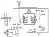
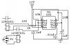
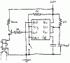
Hello, I need a timer circuit that can latch a 12V DC relay for 20 seconds every 2 hours. It can run off of 120V AC or 12V DC. If necessary, it can run off of a voltage lower than 12V by using a voltage regulator, but I would perfer to avoid that if possible. Can someone help me please? Thanks. ")
Rain
Rain