Continue to Site

Welcome to our site!

Electro Tech is an online community (with over 170,000 members) who enjoy talking about and building electronic circuits, projects and gadgets. To participate you need to register. Registration is free. Click here to register now.

  • Welcome to our site! Electro Tech is an online community (with over 170,000 members) who enjoy talking about and building electronic circuits, projects and gadgets. To participate you need to register. Registration is free. Click here to register now.

16f628 problem

Status
Not open for further replies.
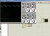
And Why does the code
Code:
   list      p=16F628A            ; list directive to define processor
    #include <P16F628A.inc>      
   errorlevel  -302 , -207    
 

       __config _CP_OFF & _LVP_OFF & _WDT_OFF &           _INTOSC_OSC_NOCLKOUT & _MCLRE_OFF & _PWRTE_ON   & _BOREN_OFF 

   Var equ 0x20
   movlw 0x10
   movwf Var

    movlw 007
    movwf CMCON
   

   BANKSEL TRISA
   movlw 0x00
   movwf TRISA
   movwf TRISB
   BANKSEL PORTA
   movlw 0b00111101
   movwf T1CON
   clrf PORTB


   Start comf PORTB, 1
   call Delay
   goto Start


   Delay Movfw TMR1H
   sublw 0xFF
   btfss STATUS, Z
   goto Delay
   clrf TMR1H
   decfsz Var
   goto Delay
   movlw 0x10
   movwf Var
   retlw 0


end

give Such waveform?
 

Attachments

  • untitled.JPG
    untitled.JPG
    124.5 KB · Views: 183
hi,
Because your sim scope is set for AC coupling on the input!
 
and what about the microcontroller? I programmed after trying 10 times and can't program now again and what's the problem in? how to solve it?
 
and what about the microcontroller? I programmed after trying 10 times and can't program now again and what's the problem in? how to solve it?

The JDM programmer has a poor reliability.
 
Yes but it programms other ones and it's working. And microcontroller is working either
 
But can't program any of 16f628's
 
So is it corrupt? Do I have to build the new one? it just consists of capacitors, resistors ad 2 transistors and what can be damaged? it programmed well for 2 days and on third day can't program them
 
Last edited:
So is it corrupt? Do I have to build the new one? it just consists of capacitors, resistors ad 2 transistors and what can be damaged? it programmed well for 2 days and on third day can't program them

The problems with the JDM is that the Vpp voltage depends upon the PC or Laptops RS232 voltage levels, these levels are sometimes too low to program the PIC correctly.
 
And how to solve it? restart PC? can't somehow I increace it? and why has it decreaced? I don't understand
 
And how to solve it? restart PC? can't somehow I increace it? and why has it decreaced? I don't understand

It needs a good power supply to provide +5V and the +13V.

extract from the designer notes:
have to carry your MCU each time when you reprogram it. The circuit is connected to the PC via serial port and no external power supply is needed. On the other hand, if you want to use it with a laptop that do not provide RS232 connection, using the circuit with a USB to RS232 converter may not give a proper result
 
Last edited:
be80be I don't understand can you explain more simply? before today, supply was enough and what happened today? restarting won't help? or what can I do?
 
Give me five and I want to make sure i read all of your post. Manly you code.
 
Try to blank the chip your configure didn't come out like you had it and I not sure you can fix it with a JDM

The var part you have made the configure write wrong


But blank the chip first and see if you can read it back


Code:
list      p=16F628A            ; list directive to define processor
    #include <P16F628A.inc>      
   errorlevel  -302 , -207    
 
       __CONFIG   _CP_OFF & _DATA_CP_OFF & _LVP_OFF & _BOREN_OFF & _MCLRE_OFF & _WDT_OFF & _PWRTE_ON & _INTOSC_OSC_NOCLKOUT
   cblock	0x20			;start of general purpose registers
    counter
   endc
  ; Var equ 0x20    this isn't right your can't use the word var
   ;movlw 0x10
   ;movwf Var
   org	0x0000			;org sets the origin, 0x0000 for the 16F628,

    movlw 007
    movwf CMCON
   

   BANKSEL TRISA
   movlw 0x00
   movwf TRISA
   movwf TRISB
   BANKSEL PORTA
   movlw 0b00111101
   movwf T1CON
   clrf PORTB


   Start comf PORTB, 1
   call Delay
   goto Start


   Delay Movfw TMR1H
   sublw 0xFF
   btfss STATUS, Z
   goto Delay
   clrf TMR1H
   decfsz  counter
   goto Delay
   movlw 0x10
   movwf  counter
   retlw 0


end
I change it But i didn't fix your delay just added where var go
 
be80be
sorry but I didn't understand well. what does it mean to blank the chip? and also, this hapened because of wrong __config? or what? I inserted the new 16f628 and it didn't work either. please write with more simple english more gramatically because I don't know much
 
be80be
sorry but I didn't understand well. what does it mean to blank the chip? and also, this hapened because of wrong __config? or what? I inserted the new 16f628 and it didn't work either. please write with more simple english more gramatically because I don't know much

hi,
You should try to ERASE [blank] the flash memory in the PIC, then try to program it with your program code.

If you have a voltmeter measure the Vpgm voltage on the /MCLR pin of the PIC while programming the PIC, tell me what you measure.
 
It was 11.06 volts and it programmed succesfully! but sometimes It did, when it stucks again, I will check the voltage and post again
 
It was 11.06 volts and it programmed succesfully! but sometimes It did, when it stucks again, I will check the voltage and post again

If its typically 11V its not high enough, check the datasheet for the recommended Vpp on /MCLR.
Being approx 11V its going to give unpredictable programming of the PIC.

Like I said yesterday, the JDM has a poor reputation, mainly because of the use of the RS232 port pins to supply +13Vpp.

EDIT:
Added programming specification.
 

Attachments

  • 000esp02.gif
    000esp02.gif
    54.4 KB · Views: 169
Last edited:
This is all I know the code you posted was setting the configure fuse wrong. It's not what is should be going by what you have in your code.

It set it to a RC oscillator not internal
This is what it did RC oscillator: CLKOUT function on RA6/OSC2/CLKOUT pin, Resistor and Capacitor on RA7/OSC1/CLKIN

This is what it should be INTOSC oscillator: I/O function on RA6/OSC2/CLKOUT pin, I/O function on RA7/OSC1/CLKIN

But it also put it in the wrong place.

You should use( cblock) for variables not (var)

It's( variable name) that can be used

But cblock is better way to do that


Code:
       cblock 
       var_name
       endc
What is your native language?
 
Last edited:
Did you make your jdm yourself ? you can boost Vpp with a wall power supply and two transistors like this
 

Attachments

  • Vpp_booster.PNG
    Vpp_booster.PNG
    10 KB · Views: 152
Status
Not open for further replies.

Latest threads

Back
Top