Electro Tech is an online community (with over 170,000 members) who enjoy talking about and building electronic circuits, projects and gadgets. To participate you need to register. Registration is free. Click here to register now.
Welcome to our site! Electro Tech is an online community (with over 170,000 members) who enjoy talking about and building electronic circuits, projects and gadgets. To participate you need to register. Registration is free. Click here to register now.
It's not good. How bad depends on a few things like if the relay is continuous or intermittent duty? A simple solution would be to look at the coil data sheet and note the current, then consider placing a resistor in series with the coil.
Yes, it is bad. You are running a relay coil at 25% above its rated voltage. How bad depends on the application. I suggested you place a resistor in series with the coil which is a simple approach. I also have no clue where you are or what common parts are available to you? I will say 16 VAC is not a common coil voltage, note I said not common. They may exist but I have no clue where.
Background... system needs to switch to batteries when the AC fails. I have the battery charger (AL624), I have the transformer (which is a 16vac 20va) & the batteries.
I do not have a switch, at radio shack I found a 12 vac switch (but i do not remember which one).
the system will need to be tested monthly, (i was thinking of adding a toggle switch to do this, but that is after the system is working)
I know nothing of resistors, so I would not know what size o how many to get.
I know just enough to know to screw things up, or follow someone else explanation. I was hoping for help; however, I fear I maybe beyond help.
I figured to wire the positive of the batteries as normal, then the neg though the switch. also run the ac that is feeding the charger to the coil of the switch.
In my area there are not a lot of places that keep low volt switches on hand so i accept i may have to order one online
putting myself out on a limb... I've read over the FAQ found some information about resistor... I don't know if I understood it correctly but i thought i would but it down and perhaps someone could correct my mistakes.
having 16.5vac power to a 12vac at 20va would need a 4.5/(20va/16.5v) = 3.7125ohms resistance
now seeing that most of these relays only need 80 to 90% of the stated voltage to activate a 4 ohm or a black yellow black ether gold or silver resistor should provide me with the resistance to use a 12vac continuous duty relay without a problem. or am i completely wrong?
You will need a much bigger resistor than that. If you put a resistor in series with the relay coil, the voltage that is dropped by the resistor depends on the current taken by the relay coil, which is far less than the 20 VA that the transformer is capable of supplying.
You need to find how much current the relay coil takes. The resistor should be about 4.5 divided by that current. However, the inductance of the relay coil makes it a bit more complicated, and the inductance changes when the relay operates. You will have to try it out.
Yeah, if you can get a relay part number you plan to use we can likely help much more. Additionally if you can tell us the load you are switching we can likely put together a simple circuit for you to follow (build).
So why not use a 120vac rated relay on the primary side of the transformer to sense the presence of power? The things are readily available enough since they are used in AC units among other things.
Well... i'm not finding anyone locally who has a 12vac coiled relay which runs DC though the throw. So, is it a option to convert the AC to DC for the switch? (I have no clue how difficult it is to do) The Transformer is a plug in transformer so i do not have any 115vac going to the box, so i would prefer not to have to pull a different line for the switch.
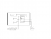
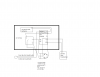
OK, let's try this again from the beginning. Try to explain what it is exactly you are trying to do. We get the part about switching from mains power to battery power using a relay in the event of power failure, would that be correct? Now a few questions are how much current are you trying to switch through your relay contacts? That is important. Especially if you are switching DC current through the relay contacts and I assume you are. Information about the battery would also help. For example it is a 12 volt 7 amp hour battery or whatever. Remember, exactly what you are trying to do. Remember we can't see what you have in mind so details are important. A drawing of what you have in mind would be nice. Even if you do it using a crayon and post a scanned image.
Your location would be nice. If you are in the US for example we can better suggest a source of parts. However, up to you.
@reloadron- yes, in the event of power failure this unit is to light 16 12v 11watt bulbs on the exterior of the building. I was thinking to have the relay complete the neg side of the circuit with the loss of AC (it was a suggestion from a alarm shop owner).
I have:
2 12v 7.5Ah batteries
1 al624 (which i am using as the battery charger)
1 16.5vac 20va plug in transformer (according to the directions for the AL624)
I am looking to have the system automatically power the lights with the loss of AC. I believe a relay is the best way to do this (i may be wrong)
I hope the drawing help...
I am currently in Provo, Utah.
I just learned my brother, whom asked me to help him with this already used this forum to ask about the same system.
OK, now I have the picture and think I remember your brother's post. You will have a few problems and here is why.
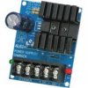
First, you have an Alltronix AL624 power supply. I have several similar units. They are designed to provide an uninterupted supply of either 6, 12 or 24 volts DC (6 & 12 volts at 1.2 amp and 24 volts DC at 0.75 amp). They also as you noted act as a battery charger to maintain the batteries. The unit you have should resemble the attached image. The AL624 requires low voltage AC to work and in this case you have a transformer delivering about 16.5 volts AC rated at 20 VA (Volt Amps). That works out to be about 1.2 amps of current.
Here is the beginning of the problem. Your outside lights are 16 each, 12 volt 11 watt lamps. That tells us 11 watts times 16 bulbs for a total of about 176 watts. Now at 12 volts that also tells us 176 watts / 12 volts = about 15 amps. Therefore under normal operation your lamps draw 15 amps of 12 volt current. That is a pretty good chunk of current.
This also tells us that under normal operation those lamps are powered from a source other than what we have covered thus far. That power is coming from somewhere? Got any ideas or thoughts as to where it comes from?
On a good day, your pair of 12 volt batteries in parallel with a full charge would be hard pressed to maintain the outside lights for maybe 30 min to an hour. I doubt you would see an hour. Now if that is acceptable, then we can go from there.
If you look close at the AC inputs to the 624 card those inputs likely go to a full wave bridge. AC In / DC Out on the bridge. The bridge output likely is across the single large cap that should be marked + / -. We can likely get some of that DC to operate a relay. When AC is present the relay will be energized and when mains power AC fails the relay will drop out. We can use a good beefy (and inexpensive) automotive relay which should be fine with voltages up to 14.5 volts or a little more. With this known relay we can then shove a resistor in series with the coil just to drop our coil voltage a little. Take a look at the 624 card and let me know if this makes sense.
we can not use the DC out of the AL624 because it does not push enough power to light the bulbs, and it is also designed to provide power regardless of AC as long as the battery hold.
batteries marked as 12V 7.5ah in a perfect world with the perfect charge will do just under and hour because of some power lose though the lines. but with the world not being perfect and batterys not holding the "perfect" charge, they will fall short by up to half.
For they time being... let use not worry about the imperfection of the world.
I do not know what a full way bridge would look like, i do know what a cap looks like. I can not find the + / - marking on the cap.
Are you suggesting to pull power from cap on the AL624 board? then add resistors based upon which 15ish amp auto relay i find?
Yes, that is pretty much what I am suggesting. Generally the cap will be marked + and - so that is weird. If you have a meter you could check the voltage across the cap and get the polarity correct.
Thank you for all the help thus far... As for auto relays I have not been able to find anything under30 amps, if this is fine thenthis is the relay I will get. If not, then I am wondering if I can use the PCLH-202D1S we already have, which is only a 10a but run the front lights though on side and the back lights though the other.
Questions:
According to the paperwork with the charger and plug in transformer I am using 18 awg wire from the power supply to the board. what size wiring should i use from the cap to the relay, or does it really matter?
Do i need to account for the power consumption of the relay in the transformer?
How do i determine the resistors needed for this relay?
I know the resistors need to go onto the positive line from the cap, however, does it matter which side of the relay coil it goes on?
This site uses cookies to help personalise content, tailor your experience and to keep you logged in if you register.
By continuing to use this site, you are consenting to our use of cookies.

")