Hi
Im building a project kit car at home and need some help.
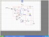
I need a very simple 12v 0 to 10 second timer. What it needs to do is this.
When the ignition is turned, a +12v will be sent from the ign-switch to the timer, activating the timer for upto 10 secs to illuminate a max 1w bulb on the dashbord then go opencircuit or switch off after the 10 secs. Similar to the way the engine management system or door lights work when you start your car.
It would be great if you could show a diagram with components so enen a idiot like me could follow and install it.
Many thanks in advance
Andy007
Im building a project kit car at home and need some help.
I need a very simple 12v 0 to 10 second timer. What it needs to do is this.
When the ignition is turned, a +12v will be sent from the ign-switch to the timer, activating the timer for upto 10 secs to illuminate a max 1w bulb on the dashbord then go opencircuit or switch off after the 10 secs. Similar to the way the engine management system or door lights work when you start your car.
It would be great if you could show a diagram with components so enen a idiot like me could follow and install it.
Many thanks in advance
Andy007
") Nice link.
Nice link.