Continue to Site

Welcome to our site!

Electro Tech is an online community (with over 170,000 members) who enjoy talking about and building electronic circuits, projects and gadgets. To participate you need to register. Registration is free. Click here to register now.

  • Welcome to our site! Electro Tech is an online community (with over 170,000 members) who enjoy talking about and building electronic circuits, projects and gadgets. To participate you need to register. Registration is free. Click here to register now.

100 LED light blinker circuit.

Status
Not open for further replies.

gary350

Well-Known Member
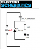
30 years ago I built 100 timer circuits using and NE-2 neon, 470K resistor, .1uf capacitor in parallel. The 100 neon blinking circuits were all powered by 1 power supply 120 vac with a bridge rectifier and cap. There is a varable resistor between the power supply and the 100 blinking lights. The 5% tolorance in the parts makes the 100 neon lights blink at different times probably 1/50 second apart but the long it runs the more random it blinks. The variable resistor changes the blinking speed from 1/2 seconds to about 5 seconds. I mounted this all on a tiny desk top Christmas tree. The drawing below shows 1 timer circuit connected to the power supply but there are 99 more timer circuits in parallel not shown. I seem to recall there is a 1 meg ohm resistor in series with the variable resistor. Never the less it works fine.

I want to do the same thing with 100 LEDs all powered by one common power supply. Is there any very simple LED blinker circuit that will blink random using minimum parts?

**broken link removed**
 
You can replace one LED in each series string with a self-blinking LED. All that series will blink. Very simple, yes. Parts count, zero.
----> **broken link removed**
If you want all the LEDs to blink at their own random, that won't work.
 
You can get LED's with built in flashers; would be random like your neon lamps but not adjustable .
 
You can replace one LED in each series string with a self-blinking LED. All that series will blink. Very simple, yes. Parts count, zero.
----> **broken link removed**
If you want all the LEDs to blink at their own random, that won't work.


A series straing of LEDs are not random they will all blink at the exact same time. But you have the correct idea anyway. I had no idea I can buy blinking LEDs but what speed do they blink ??? I like my variable speed blinkers. I want them to blink about 2 times per second. WOW i see blinking LEDs are Expensive $$$$$$ not such a good idea after all.

I seem to recall zener diodes have a reverse voltage that can be used to make a light blink when a capacitor reaches full charge then discharged through the diode.
 
Last edited:
I found info online how zener diodes work with examples and this circuit seems like it might work. Zeners come in all ratings starting at 1.8v. If I have this right the resistor slowly allows voltage to increase at the zener when voltage reaches 1.8v the LED comes on. When voltage reaches 2v zener breaks and voltage drops turing off the LED. Cycle repeats over and over on all 100 circuits in series. Maybe i use use 9v instead of 3v? Maybe there needs to me a capacitor in parallel with the LED? Do i have this right?

**broken link removed**
 
Last edited:
I found info online how zener diodes work with examples and this circuit seems like it might work. Zeners come in all ratings starting at 1.8v. If I have this right the resistor slowly allows voltage to increase at the zener when voltage reaches 1.8v the LED comes on. When voltage reaches 2v zener breaks and voltage drops turing off the LED. Cycle repeats over and over on all 100 circuits in series. Maybe i use use 9v instead of 3v? Maybe there needs to me a capacitor in parallel with the LED? Do i have this right?

No. That will not cause the LED to flash, if fact with only 3V in, it won't even light....

Here is the simplest LED flasher I know: It is a lot of parts if you need a hundred of them...

258.gif
 
Use the neon circuit you have, inserting one LED in series with each neon bulb with the cathode of each LED toward the negative terminal of the power source. If you don't like the light from the neon, paint or tape the neon bulb.

The dynamic resistance of the conducting neon bulb is about 2K ohms, limiting the LED current to below the peak value typically allowed for such a low pulse width and frequency.

I always thought NE-2s flashed on 55 volts. I tested some yesterday and it took 70 volts to get a flash. It seems to me 70v is too much for an LED. I typically attached a bridge rectifier and capacitor to the end of a 120 vac cord plug it into the wall and i get 170 VDC.
 
The LED will have no more than a couple of volts dropped across it and the rest of the voltage will be dropped across the neon bulb and the series resistors. Try it and see.
 
Here is a led blinker, not random, but true randomness is impossible.
 

Attachments

  • LED BLINKERS.pdf
    76.6 KB · Views: 189
What about utilising a random number generator circuit, and just adapting it?

Just a quick google spits out something like this, https://circuit-electronic-models.blogspot.com/2012/04/random-number-generator-based-game.html

Could replace the push button with a slower (quite a few seconds) 555 timer as the trigger. Then instead of the 7segment displays use a d-latch with LED's and just cascade as needed for the number you want. Latch the LED's on the slower 555 trigger timer as well, some of the segments will stay the same as is the nature of binary counting, others wont which will give it a random nature.

EDIT: On second thought, the wiring for this would be a pain. Haha
 
For a low voltage idea with minimum parts count, connect the 100 LEDs in a 10 by 10 matrix and drive the rows with one CD4017 and the columns with another CD4017. Between each of the outputs of the CD4017 driving the rows and the rows, themselves, insert a common emitter npn transistor with base resistor to invert the state of those outputs (Too bad they don't make a 4017 with inverted outputs.) The result is that only one row is driven low and only one column is driven high at any instant, ie, only one LED is energized at a time. Drive each CD4017 with its own, separate RC clock, the two clocks unsynchronized. The clock frequencies would be set to scan through all the possible LEDs rather quickly. Use a 5Vdc power supply and high intensity LEDs. You could use current limit resistors at the outputs of the column 4017, but you can't get much current out of the 4017 outputs anyway.
 
The transistor emitter-base with collector junctions have a fairly high voltage avalanche breakdown which produces negative resistance and is active enough to make the LED flash on and off when powered from DC.

Your low voltage zener diode has a poor zener action and does not have any negative resistance. Your circuit is completely different with a small value capacitor in a different location. Your circuit is powered from AC, not DC.
Therefore your circuit WILL NOT WORK.
 
I found the LED circuit you found. It operates the LED from the mains so it turns on and off at 50Hz and appears to be continuously lighted.
 

Attachments

  • LED lighting from 220VAC.png
    LED lighting from 220VAC.png
    21.8 KB · Views: 300
I tried the a 2N3904 transistor, the Red LED Flasher does not work on 12vdc or 15vdc.
 
Last edited:
Status
Not open for further replies.

Latest threads

New Articles From Microcontroller Tips

Back
Top