Continue to Site

Welcome to our site!

Electro Tech is an online community (with over 170,000 members) who enjoy talking about and building electronic circuits, projects and gadgets. To participate you need to register. Registration is free. Click here to register now.

  • Welcome to our site! Electro Tech is an online community (with over 170,000 members) who enjoy talking about and building electronic circuits, projects and gadgets. To participate you need to register. Registration is free. Click here to register now.

0-volt-stabilizer

Status
Not open for further replies.

Boncuk

New Member
Hi,

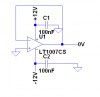
it's sometimes necessary to have stabilized 0V for an application.

After years of engineering I found the solution today.

This circuit has high input impedance and extremely low output impedance and will fit all needs. Additionally it works with AC as well as with DC.

Please don't send me flowers for that invention. ;)

A chinese semiconductor manufacturer bought the patent rights and will use the circuit in a newly designed "perhaps-gate". :D

Boncuk
 

Attachments

  • 0-V-STAB.gif
    0-V-STAB.gif
    5.1 KB · Views: 471
Last edited:
Do they offer SPICE models?

Ken
 
Last edited:
So where can I buy this ANY diode? I searched and searched but no one seems to sell one with that part number.;)
 
Last edited:
Of course this is a joke.
The diodes and the resistor are not needed. Just a piece of wire will give 0V.
 
You could do this with a micro-controller and eliminate the two diodes. :D
 
Don't forget to implement safety measures, shorting without proper limitations will result in bright light and other anomalies.

10MΩ of safety measure should suffice in almost any case. :D
 
So why can I buy this ANY diode? I searched and searched but no one seems to sell one with that part number.;)

Hi Carl,

sorry for the diode type I used in the schematic. It is available only in China. :)

Here is a revised schematic with diodes you should be able to buy in the USA. :D

Regards

Hans
 

Attachments

  • 0-V-STAB.gif
    0-V-STAB.gif
    5.3 KB · Views: 330
But what about voltage drop across the diodes? Silicon diodes drop around 0.6V so wouldn't you end up with -0.6V at the output? Using Schottky diodes will reduce this to 0.1-0.3 volts, but that's still less than 0 volts. Even better would be an op-amp follower circuit.

If you run a 0mA current source through a resistor you can get 0V as well. E = I/R so any resistance would work, except for 0 ohms, otherwise you'll divide by 0. Per a thread I posted a few weeks back, the best way to get a 0V reference is with a precision 0V reference IC. Or just use a 0V battery, also known as a "dead" battery. These can be found in any neighborhood trash can.

If you need more current, lower the value of the resistor. If you need lots of current, use thicker wires and higher rated diodes.

Note that by using a resistor (10M in the diagram) the output current will depend on the input voltage. If this is an issue, a constant current source could be used in place of the 10M resistor.

Oh yeah, one more thing. You can replace the two diodes with a single bidirectional diode. :D
 
Last edited:
I noticed that the output is shorted to GND. This is not good design practice.
Below is a method that eliminates this problem. You can probably find a better op amp than the one I chose.

EDIT: I just noticed Kpatz suggested this method. A schematic is always helpful.
 

Attachments

  • zero volt buffer.PNG
    zero volt buffer.PNG
    8.4 KB · Views: 775
Last edited:
Here's a schematic for a 0V source I found on the web.

Excellent! I got the PCB almost finished... Just a quick question... What are all those funny round thingies??? :eek:
:D
 
Lol This should eliminate the requirement of 4-20 mA signals. NO zero error.
After over 50 years of using 4-20 to eliminate error I am ussurped by 2 diodes and a resistor. Thank you.
 
Well I also have invented another useful circuit: the no-pass filter. This is the dual for the all-pass filter.

You can implement it with LC components, opamps, or digital filters.

Essentially at the input you have a low pass filter followed by a high pass filter.

For optimal operation, the cutoff frequency of the low pass filter must be at least a couple of decades lower than that of the high pass filter, and the filter's response at least third order.
 
Status
Not open for further replies.

Latest threads

New Articles From Microcontroller Tips

Back
Top