Hello,
would be thankful if someone could help me with the following:
In the problem there is only a text and it says (translated from Swedish):
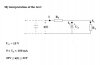
"Calculate the components in a Zener-diode stabilizer, where the stabilizing voltage is 15V. The current through the load varies between 0 and 100mA. To one's disposal there is an unstabilized voltage, which varies between 20 and 22V."
My problem in the text above, is that I'm not sure I intepret it correctly. My interpretation can be viewed in the attached image. The answer to the problem also confuses me, i.e.:
Answer: "If P is set to 3W, we get 35 < Rs < 41 Ohm"
Would be very thankful for some help here")
would be thankful if someone could help me with the following:
In the problem there is only a text and it says (translated from Swedish):
"Calculate the components in a Zener-diode stabilizer, where the stabilizing voltage is 15V. The current through the load varies between 0 and 100mA. To one's disposal there is an unstabilized voltage, which varies between 20 and 22V."
My problem in the text above, is that I'm not sure I intepret it correctly. My interpretation can be viewed in the attached image. The answer to the problem also confuses me, i.e.:
Answer: "If P is set to 3W, we get 35 < Rs < 41 Ohm"
Would be very thankful for some help here