Continue to Site

Welcome to our site!

Electro Tech is an online community (with over 170,000 members) who enjoy talking about and building electronic circuits, projects and gadgets. To participate you need to register. Registration is free. Click here to register now.

  • Welcome to our site! Electro Tech is an online community (with over 170,000 members) who enjoy talking about and building electronic circuits, projects and gadgets. To participate you need to register. Registration is free. Click here to register now.

Voltage regulator

gjoo

Member
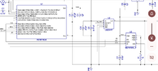
I am trying to understand the voltage regulator(lm2941t)in this circuit. I do not understand why they chose those values for r2 and r3 and what vsense does in this circuit. Also, why is 22 uf needed on the input, when the data sheet only calls for .47 uf.
 

Attachments

  • Screenshot_20230916-113641.png
    Screenshot_20230916-113641.png
    261.6 KB · Views: 128
Those resistors are not in the section of the diagram you posted.
Also, without knowing the type of power source or what else runs on that, the reason for the larger cap is just guesswork.

Post the complete diagram?
 
The asnsers to your questions on the basic configuration of an adjustable voltage regulator are contained in the datasheet. Do you have a copy of the datasheet? Have you read it carefully?

In addition it is not uncommon to have capacitors with values that differ by several orders of magnitude to serve two different purposes:
  1. A small value (0.47uF) provides a low impedance path to ground for hig frequency noise
  2. a larger "bulk" capacitor (22 uF) provides current to the regulator when the input voltage dips
 
Can you tell from the circuit why those values were chosen for the voltage divider?
To set the desired output voltage, using the formula given in Section 8.2 of the LM2941's datasheet.
 
Can you tell from the circuit why those values were chosen for the voltage divider?

To divide the output down to a suitable range for the A2D in the PIC, the PIC measures that feedback voltage, and sends corrections to the regulator using the 10K digital pot. It presumably runs a continuous loop monitoring and adjusting the regulator output voltage?.
 
But using the datasheet= 10+8/10(1.275). But, that is not right
The R2 & R3 divider is used to reduce the output voltage to a range the MCU analog input can handle. That is a common technique and separate from the output voltage control part.


The output from the LM2941 is set by U3. That's effectively a 10K pot with digital control.

It's wired as a variable resistor from LM2941 output to adjust, with the 1K resistor R1 forming the lower half of the feedback divider.

With the digital pot at zero, the output will be set to the reference, while with it at maximum (10K) it will be 11x reference, if the supply voltage was high enough.

The MCU adjusts the digital pot as needed to keep the measured voltage (via the R2 R3 divider) at whatever value is needed.
 
Being only a hobbyist, I'm still do not understand 100% why they chose the resistor values of 10k and 8k, is it to keep it around theiddle range of vdd about 2.5?
 
Being only a hobbyist, I'm still do not understand 100% why they chose the resistor values of 10k and 8k, is it to keep it around theiddle range of vdd about 2.5?

To keep it within the input range of the ADC in the PIC, which is 5V max (or less) - depending on how it's configured. This will give a maximum output voltage of 9V.
 
And that would be calculated simply by the out put of the regular multiplied by the voltage divider 10+8/10?
Simpler than that - 10 is twice 5(volts), so the 8 is twice 4(volts), giving a total of 9V - no calculation really required, just look at the values.

It helps that they have been chosen to be such convenient values - and I say 'chosen', because (for the same reason) I doubt they were 'calculated'.

Same as for converting from 5V logic down to 3.3V, just use a bottom resistor of 3.3K, and a top one of 1.8K (as 1.7K isn't a standard value) :D
 

Latest threads

New Articles From Microcontroller Tips

Back
Top