Continue to Site

Welcome to our site!

Electro Tech is an online community (with over 170,000 members) who enjoy talking about and building electronic circuits, projects and gadgets. To participate you need to register. Registration is free. Click here to register now.

  • Welcome to our site! Electro Tech is an online community (with over 170,000 members) who enjoy talking about and building electronic circuits, projects and gadgets. To participate you need to register. Registration is free. Click here to register now.

Windmill Alternator 3-Phase Rectification Circuit

Renfro

New Member
I will start by thanking you for taking the time to view my post. I am a new member here so hello everyone!

I have a windmill that has an alternator/generator consisting of a rotor that has 16 permanent magnets and 36 stator windings.

There are 3 bridge rectifiers, each having one AC terminal connected to stator windings with the other AC terminal empty. (This is the confusing part...) and the +/- DC terminals of all three bridge rectifiers are collected in parallel for DC output.

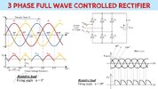
I thought that the bridge rectifier AC input terminals should be connected together in this type of "phase-phase" rectification application. See image below.

3Phase3Bridge.gif


This image shows what I expected to see however what I found in the unit didn't have the jumper/connection between the AC terminals of the bridge rectifiers. Each rectifier has one empty AC terminal.

My question is, wouldn't it be better to connect the AC input to the rectifiers as is indicated in the aforementioned schematic? or would this be a mistake? Wouldn't it provide less ripple in the DC output and more power?
 
The left and right diode pairs are in parallel, which should double the current capacity. There is no apparent reason to use only one pair, although doubling the current also doubles the off-state capacitance.
 
The left and right diode pairs are in parallel, which should double the current capacity. There is no apparent reason to use only one pair, although doubling the current also doubles the off-state capacitance.

Tony, thank you so much for your prompt and enlightening reply! It makes so much sense the way you said it and I feel a little dense for not picking up on that by looking at the bridge rectifier schematic. I tend to over complicate things sometimes.
Im definitely going to jumper those parallel rectifier pairs to decrease the individual internal diode junction temperatures and perhaps prolong the life of the components.
 

Attachments

  • maxresdefault.jpg
    maxresdefault.jpg
    121.3 KB · Views: 149
Tony, thank you so much for your prompt and enlightening reply! It makes so much sense the way you said it and I feel a little dense for not picking up on that by looking at the bridge rectifier schematic. I tend to over complicate things sometimes.
Im definitely going to jumper those parallel rectifier pairs to decrease the individual internal diode junction temperatures and perhaps prolong the life of the components.
You should also put current sharing resistors in series with each diode, to ensure equal current sharing with the paralleled diodes. Except you can't as such if you're using pre-made bridge rectifiers, although adding them to the AC inputs should work OK.

The original design is just using half of each bridge as that's all that's required - it's quite common to use a bridge in this way as they are cheap, easily available, and can be bolted down to a heatsink.
 
I have seen two bridge rectifiers instead of one, to increase the capacity on a single phase application, and each rectifier had the two AC connections joined to each other. It is a good idea to arrange the rectifiers like that so that you don't get a thermal imbalance between different bridge rectifiers. If that single-phase application had connected each AC line to both bridge rectifiers, there would have been the risk that one bridge rectifier took more current, so got hotter, resulting in a lower voltage drop, taking even more of the current, and so on.

Joining the two AC inputs will reduce the voltage drop and will increase the capacity, but it will be nowhere near a doubling of the capacity. If you look at the voltage - current curves for the rectifiers, such as here
https://www.farnell.com/datasheets/2864019.pdf on figure 3, you will see that the voltage across the diode will only be reduced by a small amount, maybe 10%, so there will still be 90% as much heat to dissipate.

I don't think that you need current sharing resistors to share the current within a single bridge rectifier, as there is very good thermal connection between the diodes anyhow. Also, the circuit has worked fine with 100% of the current being taken by one diode, at a time, so if you get an imperfect split of current, say 75% - 25%, it's only a slight improvement but it is still an improvement. Current sharing resistors would generate more heat than the reduction you would get by using both AC connections.
 
Also, the circuit has worked fine with 100% of the current being taken by one diode, at a time,
This would not be true in my case. One of the phases stopped when half of it's bridge rectifier died. After Tonys posting I moved the stator wire to the other AC terminal of the rectifier after checking those 2 diodes. This brought the unit back to life.

It sure seemed like it lost more than a third of it's DC output when that one phase was dead, maybe a x1.73 on that due to the star arrangement of the stator windings? I had noted that none of the 3 rectifiers had any thermal compound applied and there was some slight evidence of contaminant between the rectifier and heatsink surfaces I cleaned the surfaces and applied a super thin layer of arctic mx-4 i had laying around then set the rectifiers with a slight twist back and forth 1x to make a good solid thermal connection. If it goes out again I will replace all 3 rectifiers, i couldnt even find markings on these. They look like a KBPC style but I dunno if they are 1000v 50amp or 600v 35amp lol but i can get the 1000v/50a for so cheap I'd just replace all 3 and parallel the diode pairs for internal redundancy if nothing else.

So considering the 3x DC ripple frequency of the 3 phase AC to DC output of the system, this should be good to go for an inverter input at slower speeds. Or at least thats my limited interpretation lol
 
Also, am i correct in stating that the rectified DC output power would be 1.73 × One phases rectified DC output? this a product of each rectifier carrying 1.73 x it's stators generated power (to the star).
 
Would this schematic be an accurate representation of the windmill alternator/rectifier assembly if the AC source in the image as the stator windings of the unit?

3-s2.0-B9780081011249000085-f08-03-9780081011249.jpg
 
20231018_023542.jpg

20231018_023551.jpg

20231018_023655.jpg
20231018_023714.jpg


I dunno what I think of the factory wiring lol! Those indoor pushfits on the stator windings. they collected the DC from the phases with barrel crimps to #6 wire. lol keep in mind this thing gets weather exposure. Overall it shows an unfounded fear of soldering and lack of electrical engineering perhaps. I love how they used some dabs epoxy to seal the pushfits and lock the conductors in. Id just solder and heatshrink tube those little piggys.
 
Im going to at least make new 10 gauge pigtails for the DC rectifier outputs using some UV/water rated 600v insulation. The existing wires had become brittle with exposure. Id say the system was designed by someone that had perhaps a good idea about engineering and welding up a 360 degree windmill but maybe not as much experience with electrical engineering and wiring practices. I am no genius but even I have issues with this being sold as a product and not a kit that someone tried to wire without soldering.
 
I should add that the manufacturer did refund the purchase after trying to resolve the issue over the phone several times. So my friend got a free wind generator but never got to use it because of the weak output caused by the dead rectifier on that phase. I am hoping this gets him going again and theres no flaky junctions in all that stator mess...Id hate to have to clean that all up, not much slack left due to the epoxied holes.
 
Would this schematic be an accurate representation of the windmill alternator/rectifier assembly if the AC source in the image as the stator windings of the unit?

View attachment 143050
Yes, ish.
The diagram show thyristors which is why the voltage jumps up each time the phases change. With a simple rectifier the changeover will be as soon as the next phase is larger.
There will not be much inductance in the output if you are charging a battery, but there will be loads of inductance in each winding.
 
It looks like it's made for the job, very sturdily built for a long rough life, it's certainly over engineered.
Or perhaps not.

In trying to determine why output doesn't appear to increase with RPM, I came up with this theory.

The manufacturer failed to electrically insulate the silicon steel sheets that makeup the alternators core. At first I just thought the rusty metal was an eye sore but some study has indicated otherwise.

As with transformers the iron core will become a winding with 1 turn. If the core is solid then the eddy currents will become significant. Isolating the sheets by coating them individually before stacking will limit the eddy currents thus allowing the device to operate efficiently.

As RPM increases, so do these wasteful eddy currents that in turn not only draw power away as heat but also "fight" the generation of power in the stator windings. Thus the system plateaus quickly and won't ever be capable of the intended output.

Toss it in the trash. :(
 
I tried to upload a short video of the windmill that turns the alternator but mpg4 formats are not allowed. Here is a screen capture from that video.

Screenshot_20231205_201555_Video Player.jpg

The windmill is turning about 120 RPM and alternator is at a 5:1 ratio so 600 RPM alternator. Power output isnt much greater than at 100 RPM alternator due to the aforementioned eddy currents.
 
The wire is flexible Litz wire to reduce skin effect losses and lower inductance and is appears to be reliably connected with strain relief. I might have dabbed PU damping adhesive on any vibrating connectors on the stator, but I expect it is dynamically balanced.
 

Latest threads

New Articles From Microcontroller Tips

Back
Top