Continue to Site

Welcome to our site!

Electro Tech is an online community (with over 170,000 members) who enjoy talking about and building electronic circuits, projects and gadgets. To participate you need to register. Registration is free. Click here to register now.

  • Welcome to our site! Electro Tech is an online community (with over 170,000 members) who enjoy talking about and building electronic circuits, projects and gadgets. To participate you need to register. Registration is free. Click here to register now.

Waterfall Printer simulator

Status
Not open for further replies.
What is the spec on the solenoids u have? As far as I have seen 20 to 40ms is the best u can hope for.
If u parallel solenoids and add another output routine to your code u can halve the response times. But at around $10 to 15 for a solenoid it get's pricey doubling up on those. Also adds more chance of a solenoid failure.

Hi,
Attached is the Close-up picture of the solenoids i am using for this project..Thanks God they have mentioned 24VDC and 260mAmp unless i would have no clue.... The company logo is unknown and i searched on the Internet for the specifications but all efforts in vain.

How does the Output work:
1- The software send byte by byte data, the microcontroller when receives 5-bytes of data it spit-out to Shift registers which then energize respective solenoid valves.
2- All solenoid valves work in parallel.

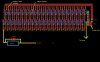
I am thinking of using 33Volts power supply to operate the 24VDC solenoid. For this i will use 47Ohm 5Watt resistors along with 50V 100mfarad capacitor to inject High current to the solenoid. This will increase Solenoid response time.
Attach picture shows the additional PCB for increasing response time of Solenoids.

PS:
Being a mechanical engineer, I do not know much about electronics so my assumptions may be wrong.
Ohhh.. I do not have Oscilloscope to check the charge/discharge timing of 50VDC 100mF capacitor to fine tune the response time and get the optimized value of capacitor. ;)
 

Attachments

  • 2.jpg
    2.jpg
    98.3 KB · Views: 309
  • capacitor resistor sketch.jpg
    capacitor resistor sketch.jpg
    122.9 KB · Views: 354
Looking very good Khalid!
Your solenoids are made by the Korean company (Keyo Wan in English spelling) if that is of any help.
 
Looking very good Khalid!
Your solenoids are made by the Korean company (Keyo Wan in English spelling) if that is of any help.

BeeBop. thanks for motivating remarks and information about the solenoid company but i could not found the decent helpful informations from internet...
 
Hi RMMM,
For the time being 'NO' but may be after some time testing my waterfall and further additions of some functionalities 'YES'... As i am involve in lot of other projects and also OFFICE work too, so it will take a little time...Some of my other projects here:
My Woodwork
Laser Scanning
 
Well, get moving then! Cant wait forever! ;)

Just kidding. It would be nice to have the software to work with, but you are the author. When you feel it is ready for release, you can release it.
 
Khalid:
I guess u are using some form of flyback transient spike control on the solenoid drives. Be aware that a simple diode flywheel introduces SIGNIFICANT lag on shut off.....up to 9 ms. Consider using a 24V Transorb in series with the flywheel diode, matching anode to anode or cathode to cathode depending on your switching polarity.

With 40 solenoids at about a 1/4 A each....that's a 10A max draw at 24V. Sounds like a couple of PC power supplies in series would be the ticket. Use At least #22AWG wire on the solenoid circuit and use a #16 or #18 AWG as the wires from the power supply. This reduce voltage driop and may impact your solenoids performance.

If u parallel 2 solenoids feeding a single tube for each water stream you can halve the solenoid response times with appropriate solenoid drive coding. This also doubles the number of MOSFET drivers and MCU drive lines unless some creative multiplexing is applied.
 
Last edited:
Hi Mosaic,
I am using IN4007 across the Solenoid to prevent High spike back voltages that can damage the MOSFETS... and You are right one of my friend "Mr.Roman" also suggested me to remove the IN4007 across the solenoid..His theory is that the IN4007 creates lag in shutdown of the solenoid valves... I will experiment by removing the IN4007 from the solenoid and will check whether this will effect the response time or just will blew-off the IRF540.. If IRF540 damage i will then use IRF840 .. I can also see replacement of IN4007 with any other fast switching diode ...

As i am very newbie to this electronic stuff i will be happy if you can post a SKETCH of installing Transorb in the circuit to understand... I am using 33 VDC 12 Amp regulated Power supply to control the system considering worst case scenario of opening of all 40 valves.. 40 x 260mAmp=10.4 amp.

Currently i am using only three digital pins of ATMEGA 328P to control 5 SIPO shift registers.. One pin is for CLOCK, the 2nd Pin is for DATA, and the 3rd pin is Latch.. If i use 4 pins of microcontrollers as DATA pins then i can reduce the time/4.

Mosaic, I am thankful for your very valuable post on the subject and i hope with all of your help we will make this complete system very low cost upto Hobbiest level.
 
Last edited:
Mosaic,
The article is very interesting to read...I am still puzzled is the simple 24V zener is enough across the solenoid or I have to add the IN4007 and 24V Zener together?
 
For a unidirectional transorb it depends on the required standoff voltage vs clamping voltage. For a unidirectional to work alone you'd need to have the stand off voltage to be about 20% higher than the expected supply voltage. This means that the transient clamping voltage would be even higher than that. To keep it simple include the rectifier. Also use 1n4001 type rectifiers if u can, they switch much faster than 1n4007, otherwise a schottky diode could work in place of the rectifier. Alternatively you could use a bidirectional transorb and no rectifier.
 
Mosaic...I will try soldering IN4007 alone across all solenoid valves..Tomorrow is the wiring and piping day... I want to complete the system as soon as possible irrespective to this thing work or not...but at least i would have a waterfall at my home ;)...
Thanks for sharing the knowledge and generous help...
 
Last edited:
Khalid I am anxious for u to succeed, as I already have a regular water feature placed in an old doorway.....I'd hope to build this project and have it going, perhaps with some RGB LED lighting FX. The 1n4007 will work. Only if u want to decrease the solenoid shut off time will you need to look at the transorb. The only way to know is to run graphics through and see how it looks. G'luck with the wiring & piping!.
 
Today i did wiring work from solenoid valves to microcontroller. Tomorrow is D DAy... lets see whats happen...
**broken link removed**
 
Hi,
I am attaching the VB6 source code and Arduino sketch for all who want to improve this program . I will request maintain my name in the 'About Box' and wherever you share keep following information in it.

Khalid Farooq Khattak
engr.khalid.khattak@gmail.com
Pakistan"

I will also request you as i have no time to work on this project and the code is not maintained in well formatted, so forgive me for this.
You can open the project in Visual Basic 6. Keep improving the program and keep posting the updates.
Regards
 

Attachments

  • VB6 Graphical Water Fountain source code.zip
    17.8 KB · Views: 241
i am very interested in this project but i cant get the program to run. i have visual studio express 2013 any help would be awesome
 
wow looks great!!! i have a strong backgound in industrial automation so the mechanical side i am comfortable with but running code for a pc I'm DOA :(. Would you be willing to release your program?
 
Status
Not open for further replies.

Latest threads

New Articles From Microcontroller Tips

Back
Top