Hello everyone I'm new to the forum and I just start my electronic journey so I’m gonna ask easy/obvious questions (not for me). Hope to learn basic and who knows what else. So if you can help me to understand those things gonna highly appreciate it, maybe one day I will be able to pass knowledge to someone else. End of introduction myself so my case is about this diagram:

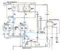
I would like to understand current flow of this car headlight wiring as want to solve the problem in same time. In this case when I switch to ON low beam lights doesn’t works at all, but high beam works. Please correct me if I get this wrong. This orange arrows represent my vision how current flows when switch is in off position

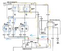
I have done reaserch and what I find out so far it's Combination light stalk that is connected to combination light switch. issue with earthing. My idea was to bypass circuit to make it works like blue arrows shows:

Let me know if :
a) my understanding of this is correct/ totally wrong (if so why)
b) bypass gonna works
c) how to include earth (pin 12) to make it works
And first of all sorry for bad drawing, was doing it from my tablet. Thanks in advance for any interesting and constructive criticism")
I would like to understand current flow of this car headlight wiring as want to solve the problem in same time. In this case when I switch to ON low beam lights doesn’t works at all, but high beam works. Please correct me if I get this wrong. This orange arrows represent my vision how current flows when switch is in off position
I have done reaserch and what I find out so far it's Combination light stalk that is connected to combination light switch. issue with earthing. My idea was to bypass circuit to make it works like blue arrows shows:
Let me know if :
a) my understanding of this is correct/ totally wrong (if so why)
b) bypass gonna works
c) how to include earth (pin 12) to make it works
And first of all sorry for bad drawing, was doing it from my tablet. Thanks in advance for any interesting and constructive criticism
Attachments
Last edited:
