Electro Tech is an online community (with over 170,000 members) who enjoy talking about and building electronic circuits, projects and gadgets. To participate you need to register. Registration is free. Click here to register now.
Welcome to our site! Electro Tech is an online community (with over 170,000 members) who enjoy talking about and building electronic circuits, projects and gadgets. To participate you need to register. Registration is free. Click here to register now.
I want to use a PIC18LF4620 at 3.3V, but one of my sensors output an analog signal 0V-5V. Can I use a +5V Vref for the ADC on the PIC when the PIC is running at 3.3V?
Does that mean that I can't use 5V as a ref V? I was thinking of using a simple resistor V divider, will I loose any accuracy/linearity (according to the maths it should be linear)? I suppose I would have to use 1% or better resistors to limit errors if the temperature change.
I need to read/write 4 other sensors as well, and some of them only work with 3.3V max. It's only the one sensor that can only work with 5V, and I don't have to wtrite to that sensor.
IE: If I run the PIC at 5V, but the GPS can only work to 3.3V I will have to drop the V on the serial output to the GPS.
No, you can't use a Vref higher than Vdd (or at least not more than 0.7V higher, the datasheet gives the exact details).
But why would you want to anyway?, either use the 3.3V (which I presume is accurate enough?), or a 2.5V precision reference IC. Assuming you want to read 0-5V, a simple resistive attenuator on the input is all you require - but bear in mind the minimum source impedance requirements.
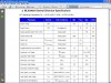
On the sensor datasheet it says: Output resistive load, minimum 200K, and max is infinity. Sensor output is between 0.5V and 4.5V.
So with a 5V input to a devider with a 1K and a 2K resistors the output will be 3.33V, but how do I work out the impedance, and the sensor output says 200K minimum?
Please see the attached screenshot of the datasheet.
No, you can't use a Vref higher than Vdd (or at least not more than 0.7V higher, the datasheet gives the exact details).
But why would you want to anyway?, either use the 3.3V (which I presume is accurate enough?), or a 2.5V precision reference IC. Assuming you want to read 0-5V, a simple resistive attenuator on the input is all you require - but bear in mind the minimum source impedance requirements.
The sensor has a 2.5V Vref output that I can connect to the ADC Vref, but how would I use that? The sensor output is 0-5V, with 2.5V at zero state. Do you mean I should drop the output from the sensor to give 0-2.5V and the use the 2.5V Vref?
Instead of having an op-amp buffer, can I put a small cap just before the AN input pin? To keep weight down I would prefer 2x resistors + 1x small cap rather than an op-amp circuit).
Edit to add: Just using a 3.3V swing on a 5V referenced ADC is not goin to be accurate enough.
You can simply use an attenuator to drop 0-5V to 0-2.5V, with no loss of accuracy - but it's all dependent on impedances - which is why my tutorial uses opamps as buffers.
You can simply use an attenuator to drop 0-5V to 0-2.5V, with no loss of accuracy - but it's all dependent on impedances - which is why my tutorial uses opamps as buffers.
Thanks Nigel!
I attached the datasheet for the device I am going to use, do you think I will be able to get away without using the op-amps to buffer the analog signal? (the important electrical specs are on page 5). Another spec: the max capacitive load is 100pf... the PIC ADC loads a 25pf cap, so I should be in spec on that one.
1: Use an op-amp buffer circuit like yours in the tutorial
2: Drop the 5V to 3.3V and used VDD and VCC as Vref
3: or drop it to 2.5V with the op-amp and use the 2.5V Vref from the gyro.
If I build your circuit as-is, what kind of scaling can I expect? IE: if I input a 3.3V signal, can I have a 1:1 (3.3V buffered) output. Sorry for the many questions, I don't know much about op-amps.
You just need to use an opamp as a buffer (no gain), use the 2.5V reference you already have in the chip, and two equal value resistors as an attenuator feeding the input of the opamp - I would suggest using a couple of 1% 220K resistors, so you're well above the chips load requirements.
So on the top part of my circuit make R1 and R5 220K, remove R3, and make P1 a wire link.
This site uses cookies to help personalise content, tailor your experience and to keep you logged in if you register.
By continuing to use this site, you are consenting to our use of cookies.