Continue to Site

Welcome to our site!

Electro Tech is an online community (with over 170,000 members) who enjoy talking about and building electronic circuits, projects and gadgets. To participate you need to register. Registration is free. Click here to register now.

  • Welcome to our site! Electro Tech is an online community (with over 170,000 members) who enjoy talking about and building electronic circuits, projects and gadgets. To participate you need to register. Registration is free. Click here to register now.

Voltage Regulator for a Small Motorbike, 6V AC Current

Status
Not open for further replies.
Ignore slightly what I said earlier about the brake switch being make-before-break, but it would probably have to be more expensive. The brake switch would have to have two independent contacts. One would short out the resistor when the brake was applied and the other would turn on the brake light.

This is, in essence, what we would have to do to eliminate the "die on bulb blow syndrome". So, a DPDT relay, an appropriately sized ballast resistor and MAYBE some things to power balance like converting to LEDS. A triac might work too.

Not sure we know the reserve power available on the 6V side.
 
When the points are open, the cap charges. When they are closed the CAP discharges into the coil.

Anyway, here **broken link removed** is a simple magneto ignition.
 
Last edited:
Ignore slightly what I said earlier about the brake switch being make-before-break, but it would probably have to be more expensive. The brake switch would have to have two independent contacts. One would short out the resistor when the brake was applied and the other would turn on the brake light.

This is, in essence, what we would have to do to eliminate the "die on bulb blow syndrome". So, a DPDT relay, an appropriately sized ballast resistor and MAYBE some things to power balance like converting to LEDS. A triac might work too.

Not sure we know the reserve power available on the 6V side.

Gentlemen, I'm trying to wrap my head around the ignition circuit. So...we've thrown out the idea of the taillight acting as a ballast, since it's not really in the ignition circuit. The brake light might be, but since it's only "on" when the brake is "on", so it's immaterial.

Am I right: The only purpose to putting the brake light in the ignition circuit is to reduce the part count in the bike? And just to grab a few more amps from the ignition coil? Seems like a lot of trouble for just a few more amps.

I ask, because every vintage/antique Italian moped, scooter, and a couple of motorcycles have this construction. They all have the brake light wired to the ignition circuit. I've never seen a realist explanation why.
 
The only purpose to putting the brake light in the ignition circuit is to reduce the part count in the bike?
Reckon so.
When the points are open, the cap charges.
Agreed.
When they are closed the CAP discharges into the coil
Surely the cap is then shorted directly by the points and the magneto coil is also shorted? This will change the ignition coil current and hence induce a high voltage, but I'm not convinced it's the most efficient way. I guess I'm out-voted by the MC industry ;).
 
Gentlemen, I'm trying to wrap my head around the ignition circuit. So...we've thrown out the idea of the taillight acting as a ballast, since it's not really in the ignition circuit. The brake light might be, but since it's only "on" when the brake is "on", so it's immaterial.

Usually, the "ballast resistor" is shorted out while starting. They apparently use the light bulb or "ballast resistor" at low RPM's only. If you define low RPM's as "brake light on".

It acts as a "fixed resistor" at low rpm (i.e. brake applied).

Is the brake somehow always applied when starting the bike?

If so, I can add to the above.
 
Last edited:
The bike is usually started without the brake light. So the brake light doesn't matter then? I've lost track.
I have a simple mind.
 
The bike is usually started without the brake light. So the brake light doesn't matter then? I've lost track.
I have a simple mind.

Good!

Does any of the bulbs provide license plate illumination as an auxiliary function? i.e. Does the Tail light provide that function?
{Trying to determine if a lamp was replaced by a RED LED would the license plate be RED illuminated?)

What we know:


So the MC manufacturer basically adds the lamp (a.k.a. ballast resistor) at low RPM. If we assume that when the brakes are applied the RPM is typically idle.

A good size for the resistor would be a resistance that drops 6V (the same as the lamp) or 2.4 Ohms (15 W, 6V is known); Current is 2.5A

There is an ignition winding and a 6V Lamp winding.

It's good to have a resistance at low RPM. The main effect would be to lower the coil temperature and spark output at idle and make it less likely for the points to "stick".

The MC manufacturer MAY have chosen to make the 6 VAC coil slightly smaller by 2+ Amps or about (6*2.4) Watts.

You CANNOT replace the brake light directly with an LED replacement.

A "clipping regulator" will not help you for the brake light.

6 VAC LEDS probably don't exist.

From your "lighting set", there is no power to spare. 31.6 W magneto. A 30 W headlamp and some other misc bulbs. It could not handle 15 W of stop lamp, But the stop lamp is, sort of, an intermittent load and it's nearly half of the 6V capacity.

What you MIGHT be able to do:

Change some or all of the lamps to LEDs and be on the safe side, regain 15 or more Watts on the normal lamp circuit.

Changing to LEDs might mean rolling your own like the guys with the PCB did or modifyng and existing lamp. I could probably modify a #194 replacement that I have to be 6 VAC. It has 6 LED's and two 290 ohm resistors which presumably means two strings. I could add a resistor and a diode, but with the LEDs back to back, the diode should be unnecessary. I'm not claiming that an #1157 LED replacement can be done the same way, but it's something to think about.

I didn't look at the full manual of the bike to figure out what lights could be replaced with LEDs.

You could TRY a 2.5 ohm 20 Watt resistor permanently in series and see if the bike behaves correctly at high RPM. Alternatively, you could ride with the brake light on all the time for a stretch and see if there is any significant performance issues.

The idea is to switch a new LED lamp in place when the brake switch is opened rather than closed.

Is it easy to change the brake switch to something else like DPDT or SPDT? DPDT would make it cake.

If we had to, also switch independently the 2.5 ohm resistor. No idea how to do this, so it's just "thinking out loud" at this point with the following premise. Don't change the power draw significantly on the 6V side.

So, a 5A AC rated DPDT switch for the brake light and a 2.5 ohm 20 W resistor, you could be on your way. Only to be on the safe side, gain some extra power on the 6V side. Probably a LED , bulb for the tail/brake would do it.
 
Last edited:
Alternatively, you could ride with the brake light on all the time for a stretch and see if there is any significant performance issues.
The main issue is that this would most likely kill the brake bulb ;). If the brake is applied at low rpm there's no problem, because the magneto voltage is also low; but at high rpm it's the high magneto voltage which does the damage.
It's good to have a resistance at low RPM.
Low rpm = low magneto voltage = reduced ignition coil current. So wouldn't that make added resistance unnecessary? I could see it being useful at high rpm, to prevent overloading the coil.
Pity the manufacturer didn't just run the brake bulb from the lighting coil. I see in the second schematic that the headlight houses a choke, which provides some regulation for the main lighting circuit.
 
Last edited:
Pity the manufacturer didn't just run the brake bulb from the lighting coil. I see in the second schematic that the headlight houses a choke, which provides some regulation for the main lighting circuit.

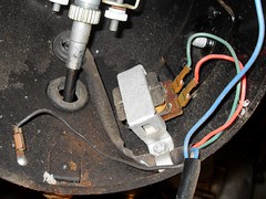
There's something in my headlight shell as well, it's not shown on the wire diagram. I didn't what it was, so here's a picture. Is it a choke? What do chokes do?

I continue to be frustrated at the paucity of the wire diagram. You need to look at both diagrams, for the two different models, to make a guess at what's going on.

15319005451_a6292c4e16_m.jpg
 
Last edited:
There's something in my headlight shell as well, it's not shown on the wire diagram. I didn't what it was, so here's a picture. Is it a choke? What do chokes do?

Yes it's a choke - presuming it's in series with the headlamp bulb?, then it will help to reduce the voltage as the engine gets faster (it's impedance will increase with frequency).

I continue to be frustrated at the paucity of the wire diagram. You need to look at both diagrams, for the two different models, to make a guess at what's going on.

To be fair (while it is poor), other motorbike and car diagrams aren't a great deal better :D
 
Nigel, I'm not sure if it's in series with the headlight. It's not on the wire diagram, and looking at the wires, it appears to be wired back to the main wire loom instead of the headlight. On the model 124 bike wire diagram, where they show the choke, it appears to be "bridging" the two coils, in series with the taillight. Does this mean it could (or should) be protecting the taillight too? If not, is putting a choke possible on the taillight to protect the bulb?

And my other question, why do all the vintage Italian small cycles put the taillight on the ignition circuit? Kiss said it was to reduce the part count. Which part(s) are they eliminating? Is that the best explanation for this odd design?

Attached is a copy of the 124 bike diagram.
 

Attachments

  • Wire Diagram Gilera_98ss-1244v-125-1505v_MO.pdf
    151.5 KB · Views: 275
Indutcor
I don't agree with the choke assessment, I believe it only affects the horn. The horn is one of the larger current devices and with an iductor, the current can't change instantaneously, so in my opinion, it "softens" the effect on the magneto. It even uses way more of the power available. I though the labels were something useful - but they are wire colors.

Parts count again

There isn't enough support for an extra 15 W in the magneto generator to support the 15 W bulb.
The 6V coil would have to be larger. Possibly the magnets would have to be larger.
They would need a ballast resistor.
They would need a different STOP switch. e.g. DPDT.

Why just braking?
I only have two possibilities:
1) At higher time closed on the points, current is applied for a longer time. The energy in the coil is proportional to current squared and time. So, at low RPM, they want to reduce the energy available to the coil or maybe they just want to slow the charging time.

2) Use the lamp as a load to provide a bit of dynamic braking. Applying a load of nearly 15W or about half the other coil's capacity would offer "some" dynamic braking. That's an angle I had not thought of before. The engine could slow down a bit more quickly.
 
I'm not sure if it's in series with the headlight.
It can be. According to the 98ss diagram the main lighting switch receives the LT coil voltage either directly via the red (rosso) wire or indirectly via the choke IM and the green (verde) wire. The switch is shown as a 3-position one (centre off) and applies this voltage to the main/dip beam filaments (azzurro and marronne wires), the instrument light LPA (bianco wire) and the tail light LPP (giallo wire). All of these bulbs will be protected/dimmed by the choke presence if the indirect route is chosen. Perhaps the dimmed lighting is intended for daylight use?
why do all the vintage Italian small cycles put the taillight on the ignition circuit?
You mean the brake light? Perhaps because the LT coil can't provide enough current for the extra 2.5A that the brake light draws, or for the reasons KISS gives, or even to drop the HT spark volts to reduce engine speed during braking.

I've been having a play with simulations of (a) a conventional car-type Kettering ignition system with the points in series with the ignition coil primary and (b) the system as per the 98ss diagram. I was surprised to find that (b) gives a higher HT voltage (I think because there's a greater current change when the points short the magneto coil). So the MC manufacturers are right and I was wrong on that score ;).
I've also come up with a possible way of regulating the brake-light voltage, using a couple of FETs. The 'regulator' (shown in the sim circuit below) clamps the voltage when it tries to go above ~6V (adjustable by resistor selection) and simply connects across the brake bulb/switch.
Ignition3.gif
 

Attachments

  • IgnitionCoil3.asc
    4.7 KB · Views: 296
Nigel, I'm not sure if it's in series with the headlight. It's not on the wire diagram, and looking at the wires, it appears to be wired back to the main wire loom instead of the headlight. On the model 124 bike wire diagram, where they show the choke, it appears to be "bridging" the two coils, in series with the taillight. Does this mean it could (or should) be protecting the taillight too? If not, is putting a choke possible on the taillight to protect the bulb?

And my other question, why do all the vintage Italian small cycles put the taillight on the ignition circuit? Kiss said it was to reduce the part count. Which part(s) are they eliminating? Is that the best explanation for this odd design?

Attached is a copy of the 124 bike diagram.

Alternators have a huge inductance. The impedance of the inductance is proportional to the engine speed, and so is the EMF. The result is that alternators are essentially constant current sources, where the current doesn't change much with engine speed.

The ignition system is typical for a magneto system, where the ignition generator coil is shorted out until a spark is wanted. When the contacts open, the current is forced into the primary of the ignition transformer (normally called a coil as well, but I'll refer to it as a transformer to distinguish it from the ignition generator coil). There is a voltage spike caused by the high rate of change of current in the primary of the ignition transformer. This voltage spike is transformed by the turns ratio of the ignition transformer, to give the spark. The engine stop switch shorts out the contacts, so the current never goes to the transformer.

Anyhow, the ignition generator coil is shorted for most of the cycle, and the current is constant. This current is used for the brake light bulb when braking, and is shorted to turn off the brake light otherwise. If the brake light bulb burns out, then there is nowhere for the current to go when braking, so the engine stops.

The lighting circuit is completely separate. When the headlight is on, the load is the two 3 W position lights and the 25 W headlight, either main or dip. This needs around 5 A, which is what the lighting generator coil produces. When the headlight is off, the additional inductor is put in series, so the current is reduced to around 1 A as the inductor will have around 4 times the inductance of the lighting generator coil.

The horn probably makes the light dim quite a lot.

It is a system that keeps the component count down, and the brightness of the lights reasonably constant, without any semiconductors or active regulators. It is as good as could be expected for the time.

If you want to change the lights using the existing generator coils, you have to keep the currents the same, give or take. With a combined tail/brake light, fed with AC, you can't rectify the current for one and not the other, and you would have to lift the earth wire. Also you would have to fit a shunt regulator in parallel if the current is less than 2.5 A, or you would have to fit a resistor in parallel. That would have the advantage of keeping the bike going if the brake light failed.

You could run the brake light from the other coil, but you would have to ground the lower end of the ignition generator coil, that goes to the brake light switch at the moment. Also your brake light switch works the opposite way round from most, as it closes when not braking.

It might be quite effective to just change all the bulbs for 12 V ones that take the same current. I did that for a 1983 Honda CG125 that had a similar arrangement for the headlight/position lights. It had a battery, which ran the horn, indicators and brake lights, but there was no regulator. I changed the lot to 12 V, with a headlight about twice the power, so similar current. I added a regulator to the rectifier.
 
Last edited:
First off, I want to thank you for shedding light on this mystery. As a hobby I collect books on moped/scooter repair, and they all dance around this subject, afraid to enter the dark den of electrics.

I can see now why the brake light is on it's own, as it's 15w is half of the lighting coil's total output. The idea of using it's current as a way of slowing the bike is interesting. I'm not sure they even thought one through.

If the choke protects both the headlight and taillight circuits, then why did the brakelight blowing? Is adding a second coil an option for protecting the brakelight, without the size or a regulator assembly?

Alec, I'm surprised your simulation says that this set up gives more voltage. The word on the street is that it's better at high rpm when the magneto is spinning, but when kick-starting, coil+battery is superior. Also, I can't open your IgnitionCoil.ASC file. What program should I use?

How about adding a choke to the brake light circuit to protect it? That seems simple and small.

Diver, practical experience of others suggest that switching to 12v bulbs is not the way to go. It exacerbates the problems. Just sayin'.....

Kiss, thanks for your expanded explanation. It's amazing that this whole subject is such a mystery to mechanics and owners. I feel like I've stumbled onto a fountain of knowledge here.
 
How about adding a choke to the brake light circuit to protect it? That seems simple and small.

Diver, practical experience of others suggest that switching to 12v bulbs is not the way to go. It exacerbates the problems. Just sayin'.....
You cannot add a choke to the brake light circuit. If you reduce the current, you will make the ignition less effective. You need to shunt the current, and a coil in parallel with the bulb would take more current at low revs, where you want to the shunt current to be similar at all revs.

I am not surprised that 12V bulbs makes the problem worse, as many will be take current than the 6 V ones. You have to have a circuit that takes the current that the ignition generator coil gives out. The bulbs may be slightly more efficient, and designed to take less current than when the bike was built. There is nearly half a century difference in ages and although tungsten light bulbs were not new in 1965, they will probably be better now. If the circuit diagram is correct, it is designed for a 6 V, 15 W bulb, so the current is 2.5 A. 12V brake/tail lights are nominally 21 W, so 1.75 A (although they might take more like 2 A). Either way, running them at 2.5 A will shorten their life.

You could just fit a resistor in parallel with the bulb to take some of the current.

If you have a true RMS voltmeter, that works at the bike frequency, you could measure the voltage at high revs, and use trial and error to find a resistor to get the voltage to around 7 V or 14 V depending one whether the bulb is 6 V or 12 V. However, voltmeters like that are not everyday items, and it is difficult to know what the engine speed is with the bike stationary as I guess that the bike has no rev counter, and if it has a speedometer, it will be on the front wheel, not the driven wheel.

Also, if you fit a resistor, the power increase in it will be huge if the bulb blows. Say you change to 12 V, and the generator produces 2.5 A, you need to bypass 0.5 A to get to the typical 2A for a nominal 21 W brake light. That needs 28 Ω, and 7 W will be dissipated in the resistor. If the bulb blows, you could get 2.5 A in the resistor and the power would be 175 W. Actually, the bike would probably stop if that happened, as there wouldn't be enough voltage for that to happen, but depending on the resistor value in comparison with the bulb, the resistor could get a lot hotter if the bulb blows.

It is all coming back to fitting shunt regulator in parallel with the brake light.
 
sign216,
There are two coils;
1) Powers the headlight and the horn.
2) Powers the ignition coil, and the taillight.

Powering the tailight off the ignition circuit was common on antique Italian mopeds, for unknown reasons. Whenever the brake light burns out, the ignition goes to ground and stops the engine.

Just to clarify, I think that there are two slight errors here. Firstly, the second coil powers the ignition and the brake light.

Secondly, when the brake light burns out, the end of the second coil that should be grounded, is not grounded, and that is what stops the engine. The brake light switch grounds that end of the coil when the brake is released, allowing the engine to run.
 
Diver:

Thanks for jumping in. It's been lonely in here.

The shunt regulator around the brake light is an option, because when the bulb blows, the regulator would take the place of the 6V drop. You don't have to design it for 10 Amps, just a nominal value of 2.5A. It will only draw the full 2.5 A when the bulb blows. Otherwise it will be doing very little UNLESS you try to make a 6 VAC replacement LED bulb.
 
alec:

I like your regulator. Seems super simple. A couple of automotive qualified Mosfets & Diodes Really clever.

sign216:
The .asc files are input to various SPICE programs. You have to have the models. Two popular free SPICE programs are TINA from Texas Instruments and LTSpice from Linear Technology. I'm not sure which one alec is using.
 
Last edited:
I use LTspice. The Yahoo LTspice User Group has freely downloadable libraries of models.
A couple of automotive qualified Mosfets
They would, of course, have to be mounted on heatsinks since they would be dissipating several Watts while the brake is on.
 
Last edited:
Status
Not open for further replies.

Latest threads

Back
Top