Electro Tech is an online community (with over 170,000 members) who enjoy talking about and building electronic circuits, projects and gadgets. To participate you need to register. Registration is free. Click here to register now.
Welcome to our site! Electro Tech is an online community (with over 170,000 members) who enjoy talking about and building electronic circuits, projects and gadgets. To participate you need to register. Registration is free. Click here to register now.
Which bulb do you blow ( tail of brake) do you know? The two filiments have different voltage ratings. It might help to know if it is time on or percent over voltage.
The Rob Hodges guy seems to know. Apparently he owns a scooter shop, and if you look at his post, he seems to be on top of it.
KISS, your theory is still a viable explanation, because Hodges probably isn't an electronics guy. But he is a scooter guy, so when he says throwing one regulator on the traditional Italian circuit won't be a solution, I've got to respect that.
Your thoughts?
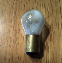
Ronv, I'll check later on which filament blew, but it was dramatic. the whole bulb was frosted white from the discharge.
The Rob Hodges guy seems to know. Apparently he owns a scooter shop, and if you look at his post, he seems to be on top of it.
KISS, your theory is still a viable explanation, because Hodges probably isn't an electronics guy. But he is a scooter guy, so when he says throwing one regulator on the traditional Italian circuit won't be a solution, I've got to respect that.
Assuming there's a single winding feeding all the bulbs, then the shunt 'regulator' you posted the schematic for would be fine - and prevent bulb failure due to excess voltage.
In my heart I think the regulator would protect the taillight, which so far has been the only light to blow. But I'm not eager to add an assembly as large as the taillight itself, to an already small bike.
I'm going to try the theory = the factory spec bulbs balance the system, and limit the voltage as designed.
So if I get all the bulbs back to specs, it should be good. If it's not, well then it's time to build a regulator.
I'm joining the party rather late, but here's another hypothesis re the brake-light/ignition wiring.
1) There's an error in that linked wiring diagram: the left end of the top coil in the magneto is incorrectly shown grounded.
2) The brake switch is a normally-closed type, so that without the brake applied, the brake-light is bypassed.
3) Applying the brake opens the switch, placing the light in series with the HT_coil primary. Both light and ignition operate (albeit with a weaker spark).
4) If the light fails open-circuit (most likely), the ignition can still operate provided the brake is not applied.
I hate typical vehicle wiring diagrams, so I've redrawn the relevant part as I think it could be in this scenario (at least, so it makes sense to me) :
That said, I think it more likely that the brake switch is a normally-open type (perhaps the OP can confirm that?) and that the wiring diagram error is that the feed to the HT_coil primary should be taken from the opposite end of the magneto top coil from that shown. However, I don't see then how an open-circuit light would prevent operation of the ignition?
Alec_T, I'm glad you're taking a look at circuit, because I know one day I'll have to fix something on it and it's unclear. Here's a different version of the diagram, from an Italian workbook for the 98ss and 124 bikes. The 98ss is the Italian version of my bike (I have the 106ss) but for America they enlarged the engine from 98cc to 106cc (feel the power!).
The Italian diagram is more complete. For one thing, it shows the voltage transformer located in the headlight shell, that is missing in the 106ss diagram.
The functon is 100% clearer in this PDF. The lamps primary function is to act as a "ballast resistor". Used in cars so that after starting, the resistor is used as to stop pitting. To get a higher voltage during starting, the resistor/lamp is switched out. They also show the #of turns higher for the coil/points.
They get the added benefit of light. You may not have enough power for an extra lamp on the main winding.
If the points stick you get a really bright bulb or failure of the bulb.
So, if your using an #1156, #1157 lamp, it's PROBABLY the wrong part. Your probably looking for a 6 V part of the correct wattage unless your manual sys differently. You COULD have drive-ability problems IF it's the wrong part. It could very well be a 15 W bulb and that might be significant IF the load was transfered to the 6V side.
So, SUPPOSE we can replace the lamp with "something" and you want to. You can probably modify LED lamps as I proposed earlier, so that the load on the original system doesn't increase with an extra LED lamp and fewer incandescents.
But, I think if you are experiencing driveabilty problems, concentrate on the right bulb and maybe new points and get driveability back.
Then questions become:
Do you want to try to increase reliability?
Why don't I see fuses?
You might end up having to design a circuit to bypass the "something" when starting and then it starts getting complicated.
Cars used the act of "starting" to bypass the ballast. This uses "braking".
Could a simple resistor work? Can we find one of those weird resistors that behave like a lamp?
Coil temperature would be a big variable to know.
Not even sure if it would be worth the effort.
Thanks for the informative links. I think you are right, the taillight serves as a ballast resistor for the ignition. This explains the odd set up of the taillight working on the ignition circuit. This oddity was never really explained on moped books and forums I've visited, but that's a good answer.
The system probably doesn't have a fuse because there's no battery. In the slightly larger model, the Gilera 124 bike, there's a battery w a fuse. For mine, it might be wise to add a fuse to the taillight, since fuses are cheaper than lights. Actually a resettable circuit breaker would be even better, but I don't know if they make one small enough for this system.
The blown light was a 6v 5/15w (5w taillight, 15w brake light), although the system really calls for a 3/15w. Do you think the slightly different spec was a reason for it to blow?
Attached is a picture of the blown light. Also attached is the bike's "lighting set" page, and also the full manual in case I'm not giving you all the info.
I agree that the second diagram is much clearer. However, IMO it also supports my hypothesis that the brake switch is a normally-closed (NC) type. That would mean the brake light only acts as a ballast resistor when the brake is applied. Can the OP confirm if the switch type is NC or NO ?
I don't believe the bulb filament resistance has any significant voltage-regulating effect. What is regulated (approximately) though, is the current through the ignition coil primary, because as the rpm increases the magneto voltage increases but so does the AC frequency and hence the reactances of the primary coil inductance and the magneto coil inductance. Simulation confirms this regulation.
The system probably doesn't have a fuse because there's no battery. In the slightly larger model, the Gilera 124 bike, there's a battery w a fuse. For mine, it might be wise to add a fuse to the taillight, since fuses are cheaper than lights. Actually a resettable circuit breaker would be even better, but I don't know if they make one small enough for this system.
Lamps rarely fail shorted, There probably is a fuseable link on the output of the generator. That's just a piece of lower guage wire.
Something weird happened. e.g. stuck points. So, it might be reasonable to inspect the points.
the OP said:
The blown light was a 6v 5/15w (5w taillight, 15w brake light), although the system really calls for a 3/15w. Do you think the slightly different spec was a reason for it to blow?
Attached is a picture of the blown light. Also attached is the bike's "lighting set" page, and also the full manual in case I'm not giving you all the info.
The importance is the 15 W and 6V for the brake light, The tail light is immaterial.
These guys, get, light, ballast, fuse out of one part, so they saved some money.
So, there really are two generators, one being a higher voltage for the coil and one to operate the lights except the brake light. Somewhat unfortunately, the lamp might blow on braking and thus a safety hazard.
I'll trow out the idea of a "second LED brake light", so you always have a brake light.
The brake light turns on, when the brake light switch "OPENS", so it's "protecting" under low RPM conditions. Meaning limiting the current and acting as a fuse.
Always carry tools to open the light and some spare lights.
I just got confused when you said the bulb was an 1157. The 1157 is a 12 V lamp.
==
I think any other light could be replaced with LED's , BUT you will have to buy, test suitability and modify them. For the #194 scenero, Add a diode, two resistors and re-arrange the string AND/OR change the direction of 1/2 the LEDs. It's a possibility, nonetheless.
When starting, the brakes are not applied, so there is no ballast, which again, makes a lot of sense.
I checked, the wire going to the brake light is normally grounded. When the brake is applied, the ground is broken. Does this help?
The bulb in there now hasn't failed, even after an hr or two of riding.
Alec, what does this mean to a layman (me): "I don't believe the bulb filament resistance has any significant voltage-regulating effect. What is regulated (approximately) though, is the current through the ignition coil primary, because as the rpm increases the magneto voltage increases but so does the AC frequency and hence the reactances of the primary coil inductance and the magneto coil inductance."
Kiss, so the brake or taillight acts a ballast resistor to protect the points or coil from getting too much current or voltage? Ok, but why wire in the brake light so that you lose ignition if the light breaks. Does that have a purpose, or is it an accident of the design?
I think 1157 refers to the socket, and not the lamp itself. So a 1157 bulb is one that fits into a 1157 socket, and can be of any voltage or wattage. An 1157 base is for dual filament lights (tail, brake). 1156 is form a simple one filament light (marker or turn signal).
I thank you so much. There's plenty of mechanics, but few are the mechanics that understand this circuit. No one does.
Kiss, so the brake or taillight acts a ballast resistor to protect the points or coil from getting too much current or voltage? Ok, but why wire in the brake light so that you lose ignition if the light breaks. Does that have a purpose, or is it an accident of the design?]/quote]
It saves a few parts.
Some examples:
The other 6V winding might have to be larger to accommodate another 15 Watts. 15/6 is more than 2 Amps. May or may nor be significant.
In order to switch in a ballast resistor the Brake switch would have to be an SPDT "Shorting" or make before break switch.
So, as you can see there are three issues related to cost:
1) Main winding size might have to be larger (2+ amps larger) > cost
2) A ballast resistor is needed. > cost
3) The brake light switch would have to be make before break. e.g. The resistor switches in before the closed contact is removed. > cost
Thoughts:
A) It might not be "that hard" to substitute a ballast resistor when the lamp burns out.
-or-
B) Lowering the power consumption of the main winding so that the 15 W brake light could be accommodated. Replace lamp with a resistor.
Invert operation of the switch.
Actually, months ago I added a resistor to the brake light, thinking it would keep the engine running when/if the light burns out. The resistor failed to do that. Although perhaps I added to the wrong side of the brake wire.
Regardless, I should probably take the resistor out. It would weaken the light's output, and when/if the brake light burns out, I can keep the engine running by just using the front brake. In motorcycling the front brake is the main brake anyway.
It means that as the revs build up the effective resistance (reactance) of the ignition coil increases proportionally and thus compensates for the increasing voltage from the magneto. This stabilises the ignition coil current and protects the ignition coil, but unfortunately not the brake light bulb.
"Alec, what does this mean to a layman (me): "I don't believe the bulb filament resistance has any significant voltage-regulating effect. What is regulated (approximately) though, is the current through the ignition coil primary, because as the rpm increases the magneto voltage increases but so does the AC frequency and hence the reactances of the primary coil inductance and the magneto coil inductance."
Here https://en.wikipedia.org/wiki/Inductor there is a funky equation just about Q factor with E=1/2*L*(I^2) and time in it. So, the energy stored in the inductor will decrease with frequency. In the WIKI equation, there is a time variable i.e t1-t1, hence as frequency decreases or the amount of time the points stay closed, the energy increases. There is also an I^2 term. The bulb, essentially operates at probably close to fixed voltage, thus a fixed resistance so it lowers the I^2 term when the brakes are applied.
It's likely not operating as a current dependent resistor, but just at one point, 6V or so, so the lamp lights. So, a choice for a ballast resistor would be one that dropped 6V, the same as the bulb.
In this case, the ballast resistor or light bulb reduces the coil temperature. Think P=(I^2)*R; where I is the current through the coil and R is the resistance of the coil. If you reduce I, you reduce I^2 and therefore reduce tempearture.
I find it strange that the points as shown actually short out the magneto coil. I always thought that conventionally the points were in series with the ignition coil primary?
This site uses cookies to help personalise content, tailor your experience and to keep you logged in if you register.
By continuing to use this site, you are consenting to our use of cookies.