Hi all,
I currently have a project where I want to heat a EMI sensitive device (DUT) with a peltier module. I started with an Arduino, a MOSFET driver module (IRF520N), a lab power supply, a temperature sensor attached to the hot side of the peltier-element (TEC) and a Peltier module with the ratings (Imax = 1.9 A, Vmax=15.4 V). The system is PID controlled. During heating, the DUT was not probperly working anymore. I observed voltage peaks in the voltage after the MOSFET driver that are synchronized with the negative edge (switch off) of the PWM signal. Those are likely the interferences disturbing the DUT too much.
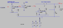
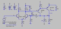
So what I require is a low ripple (unfortunatly, I am not able to specify a specific ripple value) smooth DC voltage driving the TEC. I thought about a linear voltage regulator circuit. In addition, I need to be able to adjust the voltage in a range of 0 to 15 V (at the best with the Arduino). So, I came up with the circuit attached. I plan to convert the PWM signal with a DAC to a signal adjustable from 0 to 5 V. Then I want to amplify this signal and make it the input of my voltage regulator circuit. Unfortunatly, I am not able to deliver the 15 V. I thought the buffer might help, but I would need a resistance in series with the buffer output of at least 300 Ohm (acc. to the simulation) to get a 15 V buffer output. But still, when connecting to the non-inverting input of the third op amp, it is not working.
I am (clearly) not an expert in electronics and I would be very happy about any tipps and tricks, to make my project work. Thank you!


