Continue to Site

Welcome to our site!

Electro Tech is an online community (with over 170,000 members) who enjoy talking about and building electronic circuits, projects and gadgets. To participate you need to register. Registration is free. Click here to register now.

  • Welcome to our site! Electro Tech is an online community (with over 170,000 members) who enjoy talking about and building electronic circuits, projects and gadgets. To participate you need to register. Registration is free. Click here to register now.

Very simple transmission...can't make it work

Status
Not open for further replies.

napalm

New Member
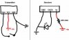
I bought this transmitter module and receiver module online and made a very simple circuit.

I think the problem is the output is TTL (transistor transistor logic), which I kinda understand. But I'm having trouble.

I should be able to press the button and have the led light up.

I included the circuit and all of the information I have on each module.
RM1SH = Receiver Module
TM1000 = Transmitter Module

The only additional information I can provide is photos of my setup. But I supplied my circuit and reference information, so I doubt it'll help you. But if you think it would, I'll be sure to include pictures. I really want this to work. Learning about wireless data transmission is hard!

Common mistakes:

The led should have a proper resistor, but I don't care if I shorten the life on it. It lights up every time I take it off the bored and test it, so I know its still working.

I don't have an antenna attached to either devices, but the range is said to be 1000m with an antenna. It should be able to do 2.5 inches without one.

Both the transmitter and receiver have the same frequency (433 MHz)
 

Attachments

  • transandreci.jpg
    transandreci.jpg
    8.7 KB · Views: 220
  • RM1SH.pdf
    81.1 KB · Views: 568
  • TM1000-1S.pdf
    96.4 KB · Views: 223
Hi,
Why do you put the resistor to the supply of the receiver?
RF module is AC coupled, isn't it? It can't send a long high or a long low signal.
See these:
 
I have a resistor because it needs 5 volts and my supply is 6. My resistor should drop it down to 5, right? Technically it can use 3-6, but they recommended 5. Or do resistors or limit current? Anyways, it doesn't work with or without the resistor.

I'm not sure if its AC coupled or not. We have the same amount of information, just those two PDF documents. How do I know if its AC coupled?
 
napalm said:
I have a resistor because it needs 5 volts and my supply is 6. My resistor should drop it down to 5, right? Technically it can use 3-6, but they recommended 5. ?

Kind of...it will only drop enough if the device drawing enough current. THat also means the supply voltage changes depending depending on the current draw of the device. A voltage flucating wildly within the operating range and a stable operating voltage are not the same thing. Use a regulator.
 
Yea, I actually happen to have a 5v regulator on my desk, not that it should matter. I don't need something permanent or stable. Just a proof of concept that I can build on later.
 
I tested my RF module by injecting 10 kHz squarewave into the transmitter data pin, then I see the receiver data pin from the oscilloscope, to check whether it is working or not.
I've tried also put a switch to the data pin of the transmitter, and a LED at the receiver; but the LED won't be turn on or off when I turned the switch on or off, the LED was just floating. So my RF module is AC coupled.
 
I don't know how to inject a square wave and I don't have an oscilloscope.

I didn't expect a transmitter with 3 pins and a receiver with 3 pins to be so confusing.

So if I my modules were AC coupled, then what do I do?
 
The Chinese datasheet doesn't have enough information to use the transmitter and receiver.

Is the output high from the receiver only a few uA of current (TTL high)? Then it won't light an LED.

Is the output low from the receiver 16mA like TTL?
Then if it goes low long enough it will light a current-limited LED. If you don't use a current-limiting resistor for the LED then the receiver, the LED or both will blow up.
 
napalm said:
I don't know how to inject a square wave and I don't have an oscilloscope.

I didn't expect a transmitter with 3 pins and a receiver with 3 pins to be so confusing.

So if I my modules were AC coupled, then what do I do?

You have to send a signal that will pass through AC coupling, my PIC tutorials have details of how to do it using PIC's.
 
I messed with the receiver circuit. Nothing was being transmitter and the led lit up. What does this mean? That the Data and Gnd terminals are linked?

The output is TTL. So when I do receive data, the Data and Vcc terminals will be linked?
 

Attachments

  • try2.GIF
    try2.GIF
    2.2 KB · Views: 176
Nigel Goodwin said:
It means the output is normally low, which is what you would expect - you might also have damaged the module by using an LED without a resistor!.
He has a resistor in series with the power supply :)
 
Nigel Goodwin said:
Even sillier idea! :p

Alright, I clearly have no clue what I'm doing.

Could you guys walk me through it or recommend a learning kit that basically does what I'm trying to do?
 
napalm said:
Alright, I clearly have no clue what I'm doing.

Could you guys walk me through it or recommend a learning kit that basically does what I'm trying to do?

Like I said above, check my PIC tutorials for examples of how it's done, or use Holtek encoder/decoder chips (which are just pre-programmed micro-controllers).
 
Am I the only one that sees irony in the name Napalm here?

Nigel's tutorials will help you but are focused on PIC microcontrollers. If you want to learn about just rf, check out http://www.rentron.com/ the site is a bit messy to navigate and it's more focused on remote control but I think you will learn a lot.
 
Hi, I've some good news for u :) . I'm working with that module for some months, and I have had no problem, except of course, that I can't make it work 1Km as the data sheet sais. I just make it work 100m. But that's another history.
Look, as bananasiong said , the module does not suport high(5V) for much time, it's just a matter of miliseconds and the output in the receiver fall(0V). So, u never gonna see the led turning on or off.
What I recomend is that you try with a microcontroler sending serial data. U will see the data going from the TX to the RX. The TX speed is up to 9600bps. I know it sounds a bit complicated, but is the only way u will see them working.
The other, of course is trying with an osciloscope and a generator.
There is some other modules, that supports slower transmitions, they are useless for my applications, but may be useful for yours,
See you
 
Ah, sth I forgot. the resistense has no sense there. You should join directly to VCC, but i recomend that you use 5V
And a little question. When you connected the transmiter to 9V, didn't it burn? I know that in the data sheer says not, but i have never done it and was affraid to break my proyect. That maybe the reason why didn't it transmit up to 1Km!!
Pls, I wait for your answer.
 
enzomagno said:
Ah, sth I forgot. the resistense has no sense there. You should join directly to VCC, but i recomend that you use 5V
And a little question. When you connected the transmiter to 9V, didn't it burn? I know that in the data sheer says not, but i have never done it and was affraid to break my proyect. That maybe the reason why didn't it transmit up to 1Km!!
Pls, I wait for your answer.
I think you can supply 9 V as long as the datasheet states it. I have a pair of RF module (different with the op). The datasheet says that the supply voltage for the transmitter can be up to 12 V.
The distance can be up to 200 feet with 9 V battery.
 
Status
Not open for further replies.

Latest threads

New Articles From Microcontroller Tips

Back
Top