Continue to Site

Welcome to our site!

Electro Tech is an online community (with over 170,000 members) who enjoy talking about and building electronic circuits, projects and gadgets. To participate you need to register. Registration is free. Click here to register now.

  • Welcome to our site! Electro Tech is an online community (with over 170,000 members) who enjoy talking about and building electronic circuits, projects and gadgets. To participate you need to register. Registration is free. Click here to register now.

The very simple circuit that the boost converter voltage from 1.5 to 12 does not work in the Proteus software...why????

electronium

Member
Greetings to the colleagues of the forum

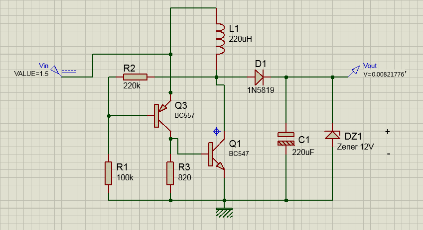
I wanted to simulate the simple circuit that I executed from the Imic site, so that I can make changes later on, the Proteus emulator file does not work.
8.16 version
The desired file of the software project

Circuit schematic file
728980631_1.5to12vedit.png.86b8f296a93179a1133d6be9f5156eab.png

circuit test video
 
Last edited:
Circuit doesn't make sense..
It's a Joule Thief type oscillator to generate a DC output from a single alkaline cell.
the Proteus emulator file does not work.
Works in LTspice (below):
Spice normally does a DC bias calculation before it does the transient response, which causes the oscillator circuit to then end up in a quasi-stable steady DC state with no oscillations.
You need to prevent that initial bias calculation by using the uic (Use Initial Conditions) command, or whatever command stops that calculation in Proteus.

1713275926384.png
 
Last edited:
That's a bad design - a large proportion of the input power will be going through Q2 collector - Q1 base & effectively shorting the source, rather than doing anything useful.

It should have a series resistor in the Q1 base circuit, possibly with a small capacitor across it to speed up switching.
 
It's a Joule Thief type oscillator to generate a DC output from a single alkaline cell.

Works in LTspice (below):
Spice normally does a DC bias calculation before it does the transient response, which causes the oscillator circuit to then end up in a quasi-stable steady DC state with no oscillations.
You need to prevent that initial bias calculation by using the uic (Use Initial Conditions) command, or whatever command stops that calculation in Proteus.

View attachment 145363
First of all, I must sincerely appreciate your knowledge, experience, and confidence, and the value you have placed on answering my challenge, so I can express my gratitude...
The second case is that I have worked with this Proteus software since university, and still, due to its complexity and bugs, I could not get the necessary benefit from this software. If there are special settings for the high frequency switching circuit software simulator Tell me about it so that we don't have such problems in the next series of circuits
 
Last edited:
That's a bad design - a large proportion of the input power will be going through Q2 collector - Q1 base & effectively shorting the source, rather than doing anything useful.

It should have a series resistor in the Q1 base circuit, possibly with a small capacitor across it to speed up switching.
Well, I sent the file to the engineer, you can edit the Q1 base which is connected to the resistor
 
Tell me about it so that we don't have such problems in the next series of circuits
I already told you what to do in the simulation.
Did you not understand?
 
What do you mean with Proteus software, it is not possible to simulate the circuit with the software's tricks and settings?
I'm not familiar with Proteus so don't know the command structure, but there should be one equivalent to the uic (Use Initial Conditions) command in most Spice simulators.
 

Latest threads

Back
Top