Continue to Site

Welcome to our site!

Electro Tech is an online community (with over 170,000 members) who enjoy talking about and building electronic circuits, projects and gadgets. To participate you need to register. Registration is free. Click here to register now.

  • Welcome to our site! Electro Tech is an online community (with over 170,000 members) who enjoy talking about and building electronic circuits, projects and gadgets. To participate you need to register. Registration is free. Click here to register now.

varioprop 12s repair

Status
Not open for further replies.

vari21

Member
hello, first of all sorry if i did post my problem in the wrong place.
.im trying to repair an old german rc radio the grundig varioprop 12S ( yellow one) i have already opened the radio and replaced the transistor t101 the one wich is connected to the 27mhz cristal quartz because when i bought it that transistor was missing i put 2N2222 instead . when i switch on the radio it turns up and i can hear the servos jiggling but not responding to the commands. when i turn it off servos stops jiggling
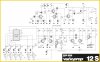
i can post pictures, and the shematics of the radio if that can help.
i appreciate any help from experts here thanks.
 
The schematics are the most important thing to post first. The pictures will be helpful if we need to tell you what components on the schematic look like. (As we have no idea of your level of knowledge of electronics.) Also letting us know what test equipment you have access to.

Les.
 
thanks les jones for your reply here is the shematics.
 

Attachments

  • Varioprop_12S-AM27_1.jpg
    Varioprop_12S-AM27_1.jpg
    193.9 KB · Views: 321
The oscillator is a Colpits oscillator. The output is taken from the collector not the emitter, but that has little effect on the oscillation.

There are two issues. One is that the base-emitter capacitor is missing. Normally there is a capacitor around 50 - 300 pF between the base and emitter. For the oscillator to work, it could have been relying on stray capacitance within the transistor.
The second issue is that the 2N2222 has a transition frequency (fT) of 300 MHz. That means that it will have a signal gain of only just above 10 at 27 MHz.

The missing capacitor would be the one that provides power from the output of the oscillator back into the crystal to sustain oscillation.

I suspect that the oscillator design is heavily dependent on the secondary characteristics of the transistor.

If you can't find the exact type of transistor used, I would suggest an RF transistor, with a much higher fT, and maybe add a 50 - 100 pF capacitor between base and emitter. Of course, if you are trying to find if the circuit is oscillating, you need an oscilloscope that can measure 27 MHz. Just testing things on the basis of overall function isn't much good in cases like this.
 
A 2n2222 might do the job, might be better with a bf199 or maybe a plain old Bc547.
You'll need to tune L101, the capacitance will be different so the resonant freq of the tank (L101 & C103) will change reducing the o/p.
If you dont have a 'scope you could throw together a Rf meter & adjust L101 for max o/p, and L103 while your at it, not brilliant but it should get you going again.
The circuit for the Rf side looks well designed & simple, sometimes though this can mean they are picky about replacement transistors.
 
When I read your first post I assumed by "radio" you meant the receiver is you seemed to be talking about servos connected to it. The schematic is for a transmitter. Was my assumption wrong or have you posted the wrong schematic ? If it is the transmitter you are working on then if you do not have an oscilloscope then you could make diode probe to detect the RF. The oscillator should be running all the time but the amplifier stage is keyed on and of by the pulse train. Shorting the collector and emitter of T103 should turn on the amplifier stage to give continuous output to the antenna.

Les.
 
sorry les jones i was nt clear ,the 3 servos are also varioprop connected to the 27mhz superhet receiver powered with 4.8 v battery pack.
i have a basic electronic knowledge level,im armed with just my digital multimeter.
 
thankyou so much diver 300 for your lights .please could you tell me what type, brand or reference of the transistor with higher ft so i can buy the right one sorry im newbie.
also i need to solder a 50/300 pf capacitor between the base and the emiter of the transistor is that correct?or please could post a drawing on how to do that.
 
hi everone
i found these transistors on ebay i dont know which one will work please diver 300 could you help
thanks again.
bf173 frequency transfer=350 mhz
bf199 frequency transfer =1100mhz
bf199 frequency transfer=750 mhz
 
Dr. Pepper's suggestion of a BF199 seems a good one. I couldn't find where to get one when I looked.

You can solder a capacitor between the legs of the transistor. Going on the back of the board is usually easiest.

Beware of fakes on eBay. The transition frequency is difficult to measure and needs expensive equipment so transistors could be mislabelled. If you can, check the gain of the transistor. Transistors with a high transition frequency often have low gain at DC. Check the data sheet for the transistor that you are buying to see what the gain should be, and if it is too high, that could be a fake.
 
I tried most of my suppliers and it seems like the Bf199 is out of favour, however cricklewood electronics have some for a quid each, handy if your in th UK.
 
It's only 27MHz, so no big deal - I used to use BC107's (audio transistor) for making VHF 'bug' type transmitters, always worked fine, their fT is 300MHz as I recall, and worked perfectly as 100MHz oscillators.

I'm a bit puzzled as to why the transistor was originally missing?, it seems rather strange - it would be extremely unlikely for it to have gone faulty. I also wasn't aware that Grundig ever made RC equipment?, and I used to work for a major Grundig dealer - but perhaps it was only a product in Germany?.
 
Agreed I have used and seen Bc547's in 100mc circuits.
 
hi dr depper and everyone, im not in uk . i found the bf199 on ebay but there are deffirent vendors so the device is defferent from a seller to another i dont know which one to get .some have 100mhz ft some have 550mhz ft ,and others have 1100mhz and some are old new stock
really confused about that. buy the way the transistor T101 mising on my pcb is CEB.
 
T101's CEB marking is most likely to be the pinout, Collector Emitter Base.
You dont know what you are going to get on ebay, new old stock sounds the best but even then they can be re labelled.
 
ok dr depper , the bc547 has 300mhz is available i will add a 50/300 pf cap between his emiter and base as he said diver300. do you think it will work.
 
ok dr depper , the bc547 has 300mhz is available i will add a 50/300 pf cap between his emiter and base as he said diver300. do you think it will work.

If there wasn't a capacitor in the circuit, it most probably doesn't need one - stray capacitance is probably all it needs. It's also likely to be a third overtone crystal, hence the tuned circuit in the collector.
 
I have used a Bc547 in a similar circuit in the order of 100mhz, I cannot say for sure if it'll work or not, however its one I would try first.
 
Status
Not open for further replies.

Latest threads

New Articles From Microcontroller Tips

Back
Top