Continue to Site

Welcome to our site!

Electro Tech is an online community (with over 170,000 members) who enjoy talking about and building electronic circuits, projects and gadgets. To participate you need to register. Registration is free. Click here to register now.

  • Welcome to our site! Electro Tech is an online community (with over 170,000 members) who enjoy talking about and building electronic circuits, projects and gadgets. To participate you need to register. Registration is free. Click here to register now.

Uhohh- Snap on multimeter repair.

michael6204

New Member
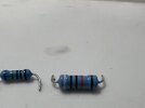
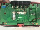
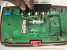
Have a question. I’m repairing a snap on multimeter that had too much DC voltage go through it and now I can’t measure dc voltage with that meter. After doing some testing I’ve found 2 resistors are dropping voltage without even having current flow. I removed and tested them and their resistance is correct but they shouldn’t drop voltage without current so I’m sure they are faulty. Everything else that I’ve tested seems to be okay. Any other likely faults? Also I can’t find replacements anywhere that are an exact match 10M .25% and 900k 1% any advice?
 

Attachments

  • IMG_9433.jpeg
    IMG_9433.jpeg
    1.5 MB · Views: 100
  • IMG_9434.jpeg
    IMG_9434.jpeg
    1.7 MB · Views: 107
  • IMG_9435.jpeg
    IMG_9435.jpeg
    1.6 MB · Views: 95
Last edited:
I had a power supply and with the meter off I put voltage on the lead of the broken meter then had my ground connected to my other meter lead and checked both sides of the resistor.
I wasn’t sure if that would be accurate bc of not having the ground anywhere in the meter circuit but on other resistors it worked as it should
 
Correct. I measured dc voltage with a good meter. The broken meter will only not read dc voltage the other functions seem to work fine. And I can’t find a schematic anywhere for this meter. I messaged the manufacturer to ask them to send me one.
 
I had a power supply and with the meter off I put voltage on the lead of the broken meter then had my ground connected to my other meter lead and checked both sides of the resistor.
I wasn’t sure if that would be accurate bc of not having the ground anywhere in the meter circuit but on other resistors it worked as it should
10M is the typical input load of a digital multimeter.

Trying to measure voltage through a 10M resistor would give you around half the input voltage with a good resistor.

Likewise, 900K should reduce it by near 10%.

The highest value resistors are usually the least likely to be damaged, as the current through them and the resulting power dissipation is very low.
 
Can you measure resistance on those parts?
 
Not a chance - I used to be a repair agent back in the dark ages for their automotive gear.

Don't know the go these days, but Snap-On gear used to have a lifetime replacement warranty.
Seems unlikely now, but they certainly used to.

Going back a LONG time they sold a nice 12V florescent tube based inspection light, a really nice item, but as is obvious they have a finite life span - giving a life time warranty meant that they were replacing them for 'ever', a friend of mine who working in a garage was continually getting his replaced.

Certainly something like a multimeter, and it's leads, would be crazy to give a life time unconditional warranty on.
 
Tony Stewart rjenkinsgb I did test resistance after removing the resistors and 1 was in spec and one was out. The problem I’m finding with them is they are dropping voltage with no current flow. Voltage should be the same anywhere in a circuit when there is no current unless there is a break in the circuit correct? Some back story, a stun gun was measured on this meter so WAY too much voltage.
 
The problem I’m finding with them is they are dropping voltage with no current flow.
The multimeter takes current to do a voltage measurement.
It's usually equivalent to 10 megaohms across an "ideal" voltmeter.

The "same voltage everywhere" only applies if the circuit resistances are low in proportion to the meter input resistance - 10M is the same as many digital meters use, so would half the reading.
(With an analog meter, you would likely get 10% or less of the input voltage, as they are generally much lower input resistance).


The voltage from a stun gun type device is high enough to arc anywhere between component leads or terminals near the lead sockets.

Semiconductors are the most likely to be damaged - resistors are very unlikely to fail unless they have been visibly overheated or charred.
 
If "no current flow." means the meter Current Mode fails, then check/replace fuse.
Everyone burns at least one. It's an unwritten Law. Otherwise Ohm's Law applies.
 
Last edited:
rjenkinsgb that’s really helpful and makes more sense. So you will have a voltage drop in a circuit if the resistance is higher or the same as the meters internal resistance? So I should be checking any semiconductors. Such as diodes or chips? Not sure how to really test the chips yet but I suppose I can use deduction if all my diodes test okay?
 
So you will have a voltage drop in a circuit if the resistance is higher or the same as the meters internal resistance?
It will exist with any circuit resistance, though in most cases the error is so small it's irrelevant.

The circuit resistance and the meter resistance act like a potential divider; eg. a 10K external resistance (to 10M meter resistance) will make a 1:1000 ratio divider, so less than 0.1% error.

1M external resistance would be 1:10 ratio so the reading roughly 9% low.
 

Latest threads

New Articles From Microcontroller Tips

Back
Top