I need to do the following for a project at uni:
Fixed frequency divider by 33. The counter used will have the synchronous R input. Only circuits will be used
from the HCT/HC series. The oscillator will provide two rectangular signals with frequencies of 5Hz and 435kHz respectively
and a manual clock signal.
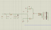
This is what I've done so far. Everything in the left side of switch 3 is mandatory. I'm new to Proteus. The simulation doesn't work, not even the first led lights up. Can someone help or give some advice please?
Fixed frequency divider by 33. The counter used will have the synchronous R input. Only circuits will be used
from the HCT/HC series. The oscillator will provide two rectangular signals with frequencies of 5Hz and 435kHz respectively
and a manual clock signal.
This is what I've done so far. Everything in the left side of switch 3 is mandatory. I'm new to Proteus. The simulation doesn't work, not even the first led lights up. Can someone help or give some advice please?