melittophily
New Member
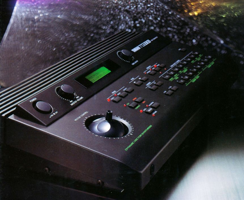
So I am looking to modify a music synthesizer here:
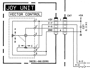
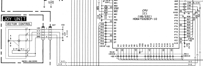
It seems clear: the +5VDC voltage source splits and goes through two 10k pots in voltage divider configuration with the middle pins respectively leading to V-X and V-Y, with a range of 0-5V, both passing through a 1k resistor and a 0.01uF cap to ground before reaching the CPU analog input pins. So a 0-5VDC control voltage signal from other synthesizer gear (LFOs, envelopes, etc) coming from a 1/8" TS jack (hot tip, ground sleeve) should be able to stand in for it.
Now this is where I feel like an idiot: I'm unsure about the cleanest way to wire up switching on this. The switching scheme is:
x jack tip signal vs x pot middle pin to V-X [then to CPU]
y jack tip signal vs y pot middle pin to V-Y [then to CPU]
I take it I should break the signal coming from the middle pin of the joystick pot and wire that into one side of the switch on a NC switching 1/8"/3.5mm jack, with the other side of the switch merged to the tip signal and going back to V-X/Y on the joystick assembly -> CPU.
Now, when thinking about this, it occurred to me that with something plugged in, it could leave the joystick discharging +0-5V to a shared ground and I'm wondering if that might cause problems. Should I use a jack that leaves the switch floating instead of grounded if something is plugged in? Maybe I'm overthinking it.
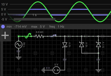
Lastly, protection. I assume a diode to block negative voltages would be a good idea. For overvoltage, would a 5V zener or schottky from tip to sleeves on the input jacks work? Most of the frequencies I use around the studio max out at 5V or a little above but accidents do happen and I don't want to fry the CPU.
I'd rather go direct than use optoisolators and have to convert input voltage to LED current to resistance back to voltage and get a slow finnicky response. I assume the R-C filter there will pull out frequencies that could harm the chip and the joystick has always had a good response to being jerked around quickly. So while isolation through a vactrol/coupler is often the safest route, it just makes the job more complex than it probably needs to be here as long as the overvoltage protection works.
It seems clear: the +5VDC voltage source splits and goes through two 10k pots in voltage divider configuration with the middle pins respectively leading to V-X and V-Y, with a range of 0-5V, both passing through a 1k resistor and a 0.01uF cap to ground before reaching the CPU analog input pins. So a 0-5VDC control voltage signal from other synthesizer gear (LFOs, envelopes, etc) coming from a 1/8" TS jack (hot tip, ground sleeve) should be able to stand in for it.
Now this is where I feel like an idiot: I'm unsure about the cleanest way to wire up switching on this. The switching scheme is:
x jack tip signal vs x pot middle pin to V-X [then to CPU]
y jack tip signal vs y pot middle pin to V-Y [then to CPU]
I take it I should break the signal coming from the middle pin of the joystick pot and wire that into one side of the switch on a NC switching 1/8"/3.5mm jack, with the other side of the switch merged to the tip signal and going back to V-X/Y on the joystick assembly -> CPU.
Now, when thinking about this, it occurred to me that with something plugged in, it could leave the joystick discharging +0-5V to a shared ground and I'm wondering if that might cause problems. Should I use a jack that leaves the switch floating instead of grounded if something is plugged in? Maybe I'm overthinking it.
Lastly, protection. I assume a diode to block negative voltages would be a good idea. For overvoltage, would a 5V zener or schottky from tip to sleeves on the input jacks work? Most of the frequencies I use around the studio max out at 5V or a little above but accidents do happen and I don't want to fry the CPU.
I'd rather go direct than use optoisolators and have to convert input voltage to LED current to resistance back to voltage and get a slow finnicky response. I assume the R-C filter there will pull out frequencies that could harm the chip and the joystick has always had a good response to being jerked around quickly. So while isolation through a vactrol/coupler is often the safest route, it just makes the job more complex than it probably needs to be here as long as the overvoltage protection works.
Last edited:
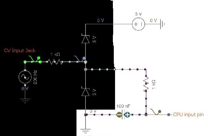
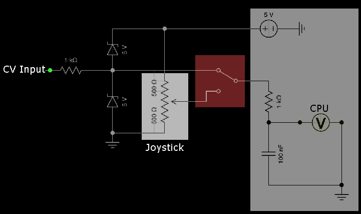
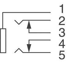
 photo of the module with the important section up front. Note joystick and headphone jack: