Continue to Site

Welcome to our site!

Electro Tech is an online community (with over 170,000 members) who enjoy talking about and building electronic circuits, projects and gadgets. To participate you need to register. Registration is free. Click here to register now.

  • Welcome to our site! Electro Tech is an online community (with over 170,000 members) who enjoy talking about and building electronic circuits, projects and gadgets. To participate you need to register. Registration is free. Click here to register now.

trying to locate crutschow...Converting -20V to 3V logic

Ches74

New Member
Hello,...
I am very curious how you were able to import the AO6408 VDMOS model into LTSPICE.
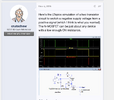
I am new to LTSPICE and trying to create a circuit you designed (see attached file) on Nov 4, 2017.
I believe you are converting a positive voltage into a negative voltage.

My end goal..is I am helping a retired friend (former supervisor) design some circuits for a 1956. Bendix Re-Build....
to translate -20V logic signals to logic +3V....so something like your circuit is where I am starting.

My call sign here is Ches74.

I really hope to hear from you...will be very cool ....thought your circuit was awesome.
 

Attachments

  • Screen Shot 2023-07-11 at 4.23.45 PM.png
    Screen Shot 2023-07-11 at 4.23.45 PM.png
    360 KB · Views: 113
Level converting a logic signal is different than what the referenced circuit is doing. A description of the actual problem with the actual levels and drive capabilities would be helpful. For example:

Convert -20V as logic 0 and GND as logic 1 to GND as logic 0 and 3.3V as logic 1. Are you catching my drift?​
ETA: Ches74 is your "screenname". Callsigns are for licensed radio operators, either civilian or military.
 
I am a licensed HAM RO...:) (call sign KI5GRI)
I have a signal -20V considered to be logic zero and 0V considered to be a logic 1.
I could get say 1-100 clocks of -20V followed by same but at 0V. This is from the Bendix computer side.
I would need to convert this signal to say where a logic "1" is +3V and a logic "0" is 0V. My apologies for the poor description as I yet dont know the full scope. Lets consider the drive load to very low for starters .....on both sides...
So this is my challenge....other challenge is I am working on getting a transistor model created and imported into LTSPICE....as its not already available in the lib. In particular...the 2N2907 from STM and AO6408 from Alpha & Omega.
 
OK, Which version of LTspice are you using. Likely choices are:
  1. LTspiceIV
  2. LTspice 17.0.36
  3. LTspice 17.1.9
I believe the 2N2907 is part of the standard distribution. I'll have to check on the AO6408, but that number also sounds familiar. Are you looking for a discrete solution to this problem?

ETA the AO6408 can be found on the site of @Bordodynov

I have a .model card for the 2N2907, but I cannot vouch for its suitability.
It is a component in the standard.bjt library in the LTspice version 17.1.9
 
Last edited:
Lets consider the drive load to very low for starters
What do you mean by low?
Is that a high impedance or a low impedance?

Below is the sim of a simple one-transistor circuit that should do want you want if the impedances are okay.
The transistor can be just about any small NPN BJT.

1689119531736.png
 
ok...Wow....I would have never guessed this solution. As I am helping out my colleague ....I have inquired about the impedance for the drive at the -20V level and +3V level. Let me check on this. I will admit I am learning about a computer from 1956....so new stuff for me.
 
gents...had long conversation on the read/write Bendix Tapes...and I have a better understanding of what my colleagues needs....he is working/explaining to me the level translation and is providing me with some specs....loads included. Appreciate you all
 
guys any helpful hints going from 3V to -20V; I am investigating the 2N2907 (pnp) I tested successfully the cathode follower from the tape reader ...so -20V to 3V works with the suggested single amp. Now going other direction.
 
Okay, here's the LTspice sim of the inverse circuit using a 2N2907 PNP to go from 0, +3V to -20V, 0V:

1689616195287.png
 
Solution
ok...I actually was setting something like this up. I am curious is this considered a Common Base Amplifier Topology? I am a CMOS IC designer....have not designed with Bipolar much../.just trying to wrap my head around the ability of the pn junctions to withstand -20V? I need to examine the large signal char....but I was curious.,,
Thanks Ches74
 
is this considered a Common Base Amplifier Topology?
Basically yes, but it's rather being used as a switch and not an amplifier.
The configuration has the advantage of allowing a control signal of one voltage polarity to generate an output signal of the opposite voltage polarity using only one transistor.
ust trying to wrap my head around the ability of the pn junctions to withstand -20V?
The collector-base junction (or collector-emitter) reverse voltage tolerance is defined by the BJT's rated Vceo maximum (which is 40V for the 2N2907, but you can readily buy BJT's with ratings of a hundred volts or more).
The base-emitter junction is only forward-biased, never reverse-biased here, so its reverse bias rating (which is typically only about 5V) is not a factor.
 
Last edited:

Latest threads

New Articles From Microcontroller Tips

Back
Top