Electro Tech is an online community (with over 170,000 members) who enjoy talking about and building electronic circuits, projects and gadgets. To participate you need to register. Registration is free. Click here to register now.
Welcome to our site! Electro Tech is an online community (with over 170,000 members) who enjoy talking about and building electronic circuits, projects and gadgets. To participate you need to register. Registration is free. Click here to register now.
If you make sealed speaker boxes then you should use speakers designed for a sealed box (very low resonance frequency). Other speakers work well in a ported speaker box if the port and box size are what are recommended by the speaker manufacturer.
In my neighbor (I dont know about other neighbor), speakers for sealed boxes very popular. Despite sealed boxes has lower efficiency, I still like it because it can create more accuracy sounds
Performance depends on your antenna and earpiece too. I used my entire metal roof and it was large, so I got VERY efficient antenna so I easily heard AM radio with many parts. However I was unable to get audio from silicone diode like 4148. I just used an cellphone earpiece (plays little louder than others) and got loud audio like a volume 1 of my cellphone. AM station is 20KM far.
AG is right- the cabinet should match the drive unit, but that is the ultimate in quality.
In my experience, the bass in a ported speaker sounds deeper, more open and natural. Also more slam if you have an amp with plenty of output current. The first time I heard this was with the Epos ESP14s (first link below). They completely blew my masive transmission lines away. On the other hand, a closed cabinet sounds, lean tight and accurate (as you say) by comparison. Depends what you want. I have been through, bass reflex, transmission line, closed box, ported. They all sound fine, but out of all those I now prefer a modern ported speaker.
Assuming that you are going for a two-way speaker: tweeter and bass:
Best to read up on port theory (see internet) and make a corresponding cabinet. Then you can experiment by either blocking off the port completely or putting foam bungs in the port to get the sound that you like, and also that suits your room. That way you get the best of all ways.
Also, mount the tweeter on a solid metal plate and mount the plate on some form of compliant material- special gel gaskets are used on top speakers.
Make the cabinet of MDF, but think about, sand, concrete... cast aluminium to deaden resonant areas. Brace the cabinet walls with steel rod or other solid material. You can make the cabinet very solid by techniques manufacturers could not afford, on cost grounds, but mainly weight. Round off corners and edges of cabinet. Test cabinet by tapping with knuckle to ensure it is completely dead- no vibrations. If it hurts your knuckle you are getting there. Glue laminate on to the MDF, inside and out. Yes, the cabinets will be heavy, but they will sound nice.
You can even think about mounting the bass driver on a solid metal plate too. Then mount the plate on to the cabinet with a compliant material, like the tweeter.
Mount the speaker cabinets on solid stands that do not obstruct the air flow: metal pipe filled with sand or concrete maybe. Once again the stands will be heavy. Height of tweeter: same as your ears when listening.
Fill the speaker cabinet with lamb's wool or similar to suit your taste. Maybe no lamb's wool.
Try using a simple cross over- just one capacitor. Use resistors to match audio power from tweeter to audio power from bass unit. Try reversing the phase of the tweeter and see how it sounds.
There are many ways to get a good sound- don't just follow your neighbour.
If all turns out well, you will have some good cabinets. Later on you can fit some drive units designed for HiFi.
I once experimented with a cabinet made from two panels of 7mm plywood spaced about 20mm apart and filled with a mixture of sand and PVA glue- never did finish it though, but that is the kind of thing I am talking about in the above post. People have also made cabinets out of fine cast concrete
Also, it's not uncommon for people to fill their commercial speaker stands with dry sand- anything to stop vibrations.
Noise, vibrations, etc are very strange. I once worked on some hand-held equipment which had to be absoloutley silent. Thre were no moving parts, like fans or disk drives and no inverters and the like. But there was a single small relay that would infrequently click on or off. You could hear it through the case, which was surprising because the case was substantial cast ally and pressurised. We thoght the solution would be simple, so we mounted the relay with a foam rubber gasket between the underside of the relay and the PCB. To our surprise the click was louder. We only managed to fix the problem by braceing the PCB with some brackets. So the message is to keep experimenting and testing.
By the way, the best way to initially set up the port damping is to get an AA battery and make and break it across the speaker terminals- a bong sound means under dampinfg and more of a click sound means over damping. You get the feel for it in practice.
By the way, the best way to initially et up the port damping is to get an AA battery and make and break it across the speaker terminals - a bong sound means under dampinfg and more of a click sound means over damping. You get the feel for it in practice.
Marble plates- Wow! That would be something. You have got me thinking again.
I have ripped out the kitchen from a house I bought recently: beautiful granite worksurface, which no one wants. I have already smashed some of it up ready for the skip (dumpster). Perhaps I will keep it after what you have said. Trouble is so many things kept and in last house no room to move. Also domestic management has a view.
Just one point, I know I said that the cabinet would be heavy but marble/granite is heavy, heavy.
For, example a piece 300mm x 300mm x 32mm is so heavy it is a job to pick up- but then you said you are a bull so that shouldn't worry you. How strong are the floors in your house.
For, example a piece 300mm x 300mm x 32mm is so heavy it is a job to pick up- but then you said you are a bull so that shouldn't worry you. How strong are the floors in your house.
I am not strong but at least I can pick up 40kg lead (I am 47kg weight-thin man )
If you asked how strong are my floor. I cant answer accurate but the foundation was made very well with bamboo stakes and reinforced concrete, the wall and 2st floor and terrace complete construct with reinforced concrete.
I have draw but not sure it good. Fill with natural cotton, I won't use lamb's wool because not cheap
(2) When I mentioned rounding off corners and side of cabinet it was the outside of cabinet I meant. This helps reduce refraction/reflections or something- can't remember exactly but good to do.
(3) Perhaps your drawing is just that, but when you actually build it is important not the have similar dimensions- your drawing looks too much like a cube- sorry. Some cabinets don't even have parallel sides.
(4) better ask your Dad to put new foundations and floor in house
In my neighbor (I dont know about other neighbor), speakers for sealed boxes very popular. Despite sealed boxes has lower efficiency, I still like it because it can create more accuracy sounds
If the enclosure and port sizes are not calculated correctly to match spec's for the speaker for a ported speaker enclosure then the accuracy might be so bad it that sounds like a "boom box" (peaked resonating bass) or no bass."
Your speaker drawing shows a hole, not a port. A port is usually a tube where its diameter and length affect its tuned frequency.
Did you see the very high cost of the British speakers?
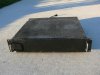
The case was made from scratch. I had access to a machine shop at the time. The cover is entirely perforated.
The rear panel has a power fuse, 2 speaker fuses, speaker terminations. isolated RCA Phono connectors and 2 non-polarized convenience outlets.
There is no power switch. My plans were to add a left clip, right clip, power and over-temp, The protect board had LED drives on it.
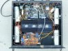
The inside:
The 4 x 9,600 uf caps were mounted with custom brackets.
There's a custom toroidal transformer under the PCB toward the front. The transformer is 4 x 35 VAC@3A . The fuseholders for the four 50 VDC supply fuseholders hang off the transformer on another custom bracket. Really close to the toroidal transformer there is another small transformer that supplies 12 VDC for the protection circuit which was designed by me. The PCB was hand done.
The protection circuit also has two isolators mounted near the inputs. There's a relay to disconnect the speakers and a relay that shorts out a line series resistor when every supply is > 2/3 of 50 V approximately. This means that if any individual supply dies (fuse blows), that flameproof resistor dies. The protection circuit could be improved. ZNR's HAD to be added to prevent my supply monitoring opto-isolators from dying.
There is no DC monitoring of the speaker terminals - just an AGX fast acing fuse. Offset is < 5 mV.
The heatsinks are massive. There are 3 diodes mounted to the heatsink. Two are basically a press-fit into holes on the heat sink and one parallel with the body on the heatsink. Having three makes it really easy to mount. They run really cool.
As designed, the boards could mount directly to the heatsink. RCA jacks were added directly to the board. Molex connectors for power and speaker allow me to remove the boards using a cable extender for troubleshooting. The protection flame-proof resistor MUST be bypassed when bringing the amp up with a Variac.
The boards are basically RF constructed with a solid ground plane on the top. Nearly all the resistors are metal film 1%. The bias adjustment is 10 turn. I accidentally made a mirror image of the PCB based on the magazine article and I was able to use the boards by switching the NPN and PNP transistors and making
My initial version had a 18 A ferro-resonant transformer (way too noisy) and the amp sounded better, I'm using a 500 W sine wave voltage regulator now, Measured, I was able to get about 100-125 W into 8 ohms, one channel driven without the regulator.
The parts list said 100 uf 50 V caps and that's what I used and one blew, hence the reason for the protection circuit. One rail died, I don;t think you can beat the sound. The output transistors are rated for a collector current of like 30 Amps. The power supply in the he Audio Magazine article specified was 3 A 70 V CT. This is too small. The speakers mentioned in the article were electrostatic, so the current doesn't matter much. Like a lot of stuff, the case and power supply use up most of the costs.
EDIT: The protection circuit (mains current limiting, AGX fuse, speaker relay, and Opto-FET in series with the input) baically does:
1) DC across speakers - AGX fuse
2) Speaker relay: Turn on/off thumps
3) Opto-FET: turn-on/off thumps, It ramps up the audio over about 10 seconds.
4) Resistor - Turn-on transients. Charging 40,000 uf of capacitance isn't good, so it charges them slowly to 2/3 of 50 V before turning on the speakers, ans starting the audio ramp.
(2) When I mentioned rounding off corners and side of cabinet it was the outside of cabinet I meant. This helps reduce refraction/reflections or something- can't remember exactly but good to do.
(3) Perhaps your drawing is just that, but when you actually build it is important not the have similar dimensions- your drawing looks too much like a cube- sorry. Some cabinets don't even have parallel sides.
(4) better ask your Dad to put new foundations and floor in house
(1) Just remove the MFD
(2) I think it is reflection. But I realize my stone plates are black granite, not marble. It too hard (natural stone much harder than artifical stone) so hard to round off or make a large hole that fit the subwoofer spkr, I only have under 15mm drill bit, no grinding.
(3) The pic was drew quickly by paint, it just a demo and have many error, the boxes must be calculate carefull, of course
(4) New foundation, lol, I think it not necessary, most houses in Vietnam have foundation design like this, some people even put 400W audio systtem in their house, not a problem.
This site uses cookies to help personalise content, tailor your experience and to keep you logged in if you register.
By continuing to use this site, you are consenting to our use of cookies.