Heres a thread I started on another forum, its very similar to yours only I built mine from a vehicle ignition coil as the whole thing runs from 12v vehicle power and a vehicle engine driven alternator, the high voltage part is a marconi oscillator.
https://www.edaboard.com/thread172613.html
Heres an article on how it works:
**broken link removed**
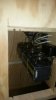
I used stack of 25 x 15 x 10 N87 ferrite cores, 10 in total I think, you can see the trans on the thread.
I metion in the thread it didnt work on an ac weld set, that was my snafu, it wasnt powered up.
To protect the weld set or alty whatever is powering the system you can put a 1u motor start cap across it, this effectively shorts out the hf and directs it to the arc.
https://www.edaboard.com/thread172613.html
Heres an article on how it works:
**broken link removed**
I used stack of 25 x 15 x 10 N87 ferrite cores, 10 in total I think, you can see the trans on the thread.
I metion in the thread it didnt work on an ac weld set, that was my snafu, it wasnt powered up.
To protect the weld set or alty whatever is powering the system you can put a 1u motor start cap across it, this effectively shorts out the hf and directs it to the arc.