EvilGenius
Member
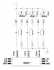
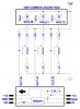
If you draw an imaginary vertical line in the middle of circuit, looking at the left side you have 21ma coming in, less transistors base currents going out and in (net 2.5ma), you get 18.5ma going out thru WS. On the right side you have 300ma led current coming in plus net base currents (2.5ma) going out. This current of 302.5ma is set by Rs, the resistor at the bottom right hand corner. The top left corner current of 21ma is set by ((12-Vbe1-Vbe2-Vws)/Rb. For red led I added a resistor in series with the led to pickup the slack between 9.6v and 6v Vf differences. This resistor is not necessary for constant current but is used to lower the transistor power dissipation. In a sense making red, green, and blue behave similarly in the circuit. Pd of load transistors are less than 300mw!
Last edited:
")