screwdriver
New Member
Hello, I'm trying to make a simple stereo amplifier for my computer, I decided to use a TDA7265 because of availability but after having tried with 3 different chips (I mean 3 TDA7265) the thing doesn't work. I can't imagine what's happening anyone could help?
When I connect the TDA7265 gets hot very soon even if there's no load and makes a humm in the loudspeaker but nothing like sound.
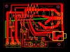
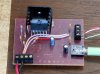
The circuit I'm building is the one that comes in the datasheet (**broken link removed**) I include here an image of the circuit built and the board:
Thank you for your help.
When I connect the TDA7265 gets hot very soon even if there's no load and makes a humm in the loudspeaker but nothing like sound.
The circuit I'm building is the one that comes in the datasheet (**broken link removed**) I include here an image of the circuit built and the board:
Thank you for your help.