Electro Tech is an online community (with over 170,000 members) who enjoy talking about and building electronic circuits, projects and gadgets. To participate you need to register. Registration is free. Click here to register now.
Welcome to our site! Electro Tech is an online community (with over 170,000 members) who enjoy talking about and building electronic circuits, projects and gadgets. To participate you need to register. Registration is free. Click here to register now.
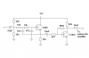
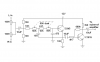
The first resistor of your Sallen-Key lowpass filter must be 10k ohms and must not be fed from another resistance. You had it in series with the volume control so the filter became messed up. I added a transistor as a low output impedance emitter-follower between the volume control and the filter circuit. This new emitter-follower also biases the first transistor in your filter. I do not know why your volume control was stereo and was odd.
50k dual pot to control cutoff frequency is correct?
I will replace 2.2uf cap with 10uf one because I don't have 2.2 but 10 too much. The 20k pot will place by 10k one
And I also want to know why you said the volume control was odd?
The dual 50k pot will allow you to adjust the cutoff frequency of the lowpass filter. But you should have an opposite filter (a highpass filter) that feeds the amplifiers for the woofer/midrange speakers.
Your 10uF capacitor will pass frequencies in my new circuit to 1Hz which is VERY low but it will work fine. The 10k volume control will be fine.
Your volume controls were not connected to ground so they would not control the volume. You used two volume controls when only one control is needed.
A volume control is supposed to be logarithmic, not linear.
The fairly low input impedance of the circuit will "load down" a 100k volume control.
Your circuit is missing mixing resistors so when your volume controls are maximum then they short the left and right channels together that might cause damage or distortion.
I know that but I never turn the volume maxium, add mixing resistor to stereo pot will spent space of the tight box, I want save space for the filter.
Damn it, C945 and C1815 has pinout B-C-E, it made me difficult to draw pcb. Why Japanese didn't use pinout like C-B-E in many 2N....... transistor ????
Most 2N.... transistors have pins that are ECB. European BC... transistors have CBE. EDIT: I got it WRONG! Their base is always the middle pin.
Here is from their datasheets:
This site uses cookies to help personalise content, tailor your experience and to keep you logged in if you register.
By continuing to use this site, you are consenting to our use of cookies.