Continue to Site

Welcome to our site!

Electro Tech is an online community (with over 170,000 members) who enjoy talking about and building electronic circuits, projects and gadgets. To participate you need to register. Registration is free. Click here to register now.

  • Welcome to our site! Electro Tech is an online community (with over 170,000 members) who enjoy talking about and building electronic circuits, projects and gadgets. To participate you need to register. Registration is free. Click here to register now.

Kinergetic Subwoofer Circuit Analysis

MLVW

New Member
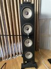
I have a pair of old Kinergetic Subwoofers (SW-100) for my stereo, which are long out of production. The speakers came with a passive control box that includes a low pass filter and circuits to compensate for the mechanical structure of the speakers. This was done in an attempt to eliminate "one-note" bass.

The control box is in short supply on the used market and the guy that use to repair them has long since retired. With DSP now more commonly available, I’d like to try and develop a DSP replacement for the control box as a community service.

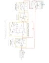
My background is physics, so I have some familiarity with circuit design, but the “Mechanical Structure Compensation Circuit”, which contains a complicated OpAmp circuit in the feedback loop is beyond my skill level.

I am wondering if anyone is able/willing to help me analyze that circuit? Alternatively, is there an advanced circuits textbook that could push me along?

What I know from reading the patent filings is that this is a feed-forward designed to compensate for cabinet resonances. So, I think this is somewhat analogous to an RIAA correction for an LP.

I am including a copy of the circuits and signal path from the patent filings. I will need to fiddle with the resisters to tune the circuit, but I need to start with an understanding of the circuit.

Thanks for any help anyone can provide, Mike
 

Attachments

  • MVW_Circuit.jpeg
    MVW_Circuit.jpeg
    177.8 KB · Views: 82
Yes HPF is correct for 3rd.

 
Last edited:
Different orders of filters give the same response if coming from low impedance sources.

You can select in/out each here
 
Tony and Crutschow:

The attached figure shows the SPL data from the analysis. The black line is the SPL from the SW800C crossover box in the signal path. This is the target curve. As suggested by Crutschow, the frequency response is indeed pretty flat from 20-150 hz and then rolls off as you would expect for a sub.

The red line is the SPL without the SW800C box. I had to apply an overall -8 db gain to the output to get the two lines to intersect at 150 hz and to keep the speakers from blowing up.

The blue line is the same as the red line but I applied a -12db/oct low pass Butterworth filter with a cutoff frequency of 150 hz to see how close I could get.

Oddly, it looks like the low-freq roll off is about 7 db/oct, but I suppose I can boost the signal and then tinker with a 6db/oct filter to get close.
 

Attachments

  • SW800C_setup.jpg
    SW800C_setup.jpg
    77.7 KB · Views: 40
  • SW800C.jpg
    SW800C.jpg
    85.2 KB · Views: 40
So it does look like a 6dB/octave boost from a 1-pole LP slope, will give a reasonably flat response down to 20Hz.

Below is the LTspice sim of an example circuit for that:
It has a 2-pole Sallen-Key HP filter for subsonic rolloff, followed by a 1-pole LP filter with a DC gain of 20db to give the sub frequency correction.

1710701678273.png
 
Last edited:
Worked slick as a whistle! Thanks for the help. Data always rules
So did you generate the HP and LP functions with your DSP circuit?

Can you post a plot of the speaker response with that compensation?
 
Crutschow: SW800C shows the target transfer function (black) and the raw data without the SW800C (red). Note that I used the DSP (not the preamp) to dramatically reduce the gain until I figured out the appropriate range. I then applied a ramp filter to the signal [SW800C(a) & (b)]. That brought down the signal at higher frequency, so I then boosted the overall gain. In actual fact, I didn't need any additional gain (0 db) because the two curves matched at 20 hz.

I then applied a 12 db/oct low pass BW filter with a cut-off freq of 120 hz to match the settings in the SW800C box (the blue line is based on a 150 hz cut-off freq).

The final results are shown in SW800C-Transfer-Function. Again the black curve is the target from the box and the red curve is the DSP equivalent. Pretty darn close. Note also that I was running my main speakers, so you don't see the fall-off at 120 hz.
 

Attachments

  • SW800C.jpg
    SW800C.jpg
    85.2 KB · Views: 34
  • SW800C(a).jpg
    SW800C(a).jpg
    79.7 KB · Views: 32
  • SW800C(b).jpg
    SW800C(b).jpg
    84.6 KB · Views: 31
  • SW800C-Transfer-Function.jpg
    SW800C-Transfer-Function.jpg
    98.3 KB · Views: 33
And even with the box, I have applied a HP filter with a cut-off freq 18 hz to knock down the subsonic's, but for the most part that hasn't been an issue for music. But I shouldn't forget about that.
 
Last edited:
Looks pretty good for an interior room with reflections. There's bound to be some phase cancellations at some crossover point.

Outdoors would be a different plot. But you'd have to be on the roof of a skyscraper or a farm to enjoy that.
 
Yes, dealing with phase cancellation at the crossover is an issue even with the SW800C. I did have to fiddle with the phase at the crossover, but I needed to do that regardless. I could also do some fine tuning down the road, but for now I mostly wanted to get a handle on the big picture.
 
Your ROOM frequency response curve is not flat due to phase cancellations and additions caused by the different sound distances caused by room reflections.
The crossover circuit should already have the phases of the woofer, mid and tweeter speakers zero'd at their crossover frequencies.
 
I am using panel speakers, so there isn't an actual mid/tweeter crossover. But I am using the DSP to roll-off the bass from the panels. The SW800C provides the crossover for the woofers. Indeed it isn't perfectly flat. There are some room modes and other aberrations that I have largely EQ'd for my normal listening, but I didn't want to mix a bunch of other corrections into the basic analysis and loose sight of the goal.
 

Latest threads

New Articles From Microcontroller Tips

Back
Top