Electro Tech is an online community (with over 170,000 members) who enjoy talking about and building electronic circuits, projects and gadgets. To participate you need to register. Registration is free. Click here to register now.
Welcome to our site! Electro Tech is an online community (with over 170,000 members) who enjoy talking about and building electronic circuits, projects and gadgets. To participate you need to register. Registration is free. Click here to register now.
What crutshow said is exactly what I wanted to get you to think about. There is a calculus formula for RMS and it essentially means waht it says: the sqrt of the average of the square. It's done by numerical integration e.g. newton's method of the waveform.
That gets you the numerical value of the RMS voltage and the numerical value of the RMS current. You have to have enough samples to make the calculation correct. Peak detection is going to be problematic.
Phase angle might be a bit harder, but for sinusoidal waveforms it should be easy.
For a sine waves P = V*I * cos(theta).
You should take a look at some of the power metering chips that are available.
I think the quantities your interested in are:
RMS value of V
RMS value of I
and the RMS value of V * I
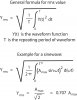
(Use the Calculus formula for RMS). It has terms like: 1/(b-a) * integral of (something) dt.
Now you can see where real and aparent power and power factor come into play.
What crutshow said is exactly what I wanted to get you to think about. There is a calculus formula for RMS and it essentially means waht it says: the sqrt of the average of the square. It's done by numerical integration e.g. newton's method of the waveform.
You are making it more difficult than it is. If you multiply the instantaneous voltage by the instantaneous current and average the result over a complete cycle, you get the RMS power directly. You don't need to calculate the RMS value of the voltage and current. No calculus needed.
>I think the quantities your interested in are:
>RMS value of V
>RMS value of I
>and the RMS value of V * I
Exactly!
So let me go one step further. I have a research facility that will design a circuit for me which will be providing me with clean V and I values. But I don't remember what was said at the meeting... as to which one they will provide me... peak instataneous values of V and I *or* RMS V and I.
Having said this, I just don't get something. If they provide me clean peak instataneous values of V and I, then I would have to use your calculus formula to get my RMS values right?
But let's say that the peak V and I signals they provide me are super clean, what stops me from taking 0.707 of these values to get my RMS values? And then use:
For a sine waves P = V*I * cos(theta).
and go from there to get all my other power values?
So we've established that obtaining the true power value is pretty easy (and no calculus required).
But the hard part is still going to be determining the actual phase angle so you can derive power factor. How are you going to go about this? Remember that if you look for zero-crossing points, this is going to be complicated by any significant distortion of the sine wave (e.g., if the signal takes a "double dip" above or below zero).
Sorry, But you need RMS of V and RMS of I to get power factor and RMS of V * I
If the signals are super clean and you take the Nyquest theorem seriously (either line frequency or sample frequency), you would still need timing info if you had the peaks. Signal period (frequency isn't always 60 Hz), peak I, peak V, when the peak occurred) and we ASSUME it's a pure sine wave.
If you timed the difference between the current and voltage peaks and know the frequency, you could determine phase angle. For the power line, the frequency is not constant. Pretty close to a constant, but not a constant. There are experiments being done to make it more sloppy and plants have had to install generators to compensate.
The Calculus is noting but multiplying and summing. Numerical integration is the sum of all the little rectangles under the curve.
e.g. sum(v(t) * i(i) delta(t)); since it's rms, the bottom part of the wave form is fllipped, so everything is positive. Now you have to divide that integration by the total time.
So now you have other issues: Is this an energy meter? What interval will power be taken over ( average over last 10 cycles)? What interval will "instantaneous power" be taken from (1 cycle)?
Boy this is getting out of hand. Okay, so you are saying that if I read in one full AC cylce at the rate of one read for every 10 milli seconds (allowing me to have 100 values) of volateg and current stored in my controller. And then multiply every voltage value with its corresponding current value, add them up and divide by 100 to get the average, I will end up with the rms power which is true power right?
>But the hard part is still going to be determining the actual phase angle so you can derive power factor. How are you going to go about this? Remember that if you look for zero->crossing points, this is going to be complicated by any significant distortion of the sine wave (e.g., if the signal takes a "double dip" above or below zero).
I would be constantly reading in the values. How often is an AC signal going to "double dip". There could be conditions as to weather that particular cycle is to be discarded or not based on sudden changes of this sort! No?
Possibly. It depends on just how distorted the sine waves get. Others with real-world experience with this will have to comment.
By the way, meta-note: You can use "Reply With Quote" and not have to copy the replied-to text by hand (plus it gives time and respondee attribution). Just a hint.
>So now you have other issues: Is this an energy meter? What interval will power be taken over ( average over last 10 cycles)? What interval will "instantaneous power" be taken >from (1 cycle)?
Its just to measure true power. It would be nice to measure the other powers simply for statistical purposes along with the power factor. But its just to get a true power reading once every 10 seconds! That's all.
>e.g. sum(v(t) * i(i) delta(t)); since it's rms, the bottom part of the wave form is fllipped, so everything is positive. Now you have to divide that integration by the total time.
Okay! Calculus was an amazing class. 20 years ago. Now, I need review to galore! LOL.
okay so:
>sum(v(t) * i(i) delta(t))
v(t) is voltage at time slice?
i(i) is current instantaneous?
delta(t) is the time interval right?
If its okay with you, can you do provide a simple example with real numbers.
It's actually easier that it looks. Let's do it briefly for V
Determine what the time slice should be. Might have issues at the end points because of not exactly 60 hz
Get the zero crossing, this is time t=0
Say every 0.1 mS (crude), v =0
t=(0.1), v = 1 for example
Area under curve=0
This assumes V(t) is positive
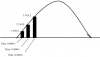
You sum the area of the trapezoid containing (0,0) and (0.0001,1)
You do the next trapezoid (0.0001s, 2V) and (0.0002, 3 V) This isn;t a sine wave
and add it to the previous one.
Now let's say that the last sample is negative. You'll have to figure out how to handle that.
Or, you can make the voltage/current always positive and work from there. So, you can see the time slice matters. At the ends, it could be a little bit you might miss.
Okay, I really appreciate you helping me here.... So getting back to what you were explaining:
>The Calculus is noting but multiplying and summing. Numerical integration is the sum of all the little rectangles under the curve.
>e.g. sum(v(t) * i(i) delta(t)); since it's rms, the bottom part of the wave form is fllipped, so everything is positive. Now you have to divide that integration by the total time.
>You sum the area of the trapezoid containing (0,0) and (0.0001,1)
>You do the next trapezoid (0.0001s, 2V) and (0.0002, 3 V) This isn;t a sine wave
>and add it to the previous one.
So in my attachment, is pretty much what you have explained. So what is it that I should do exactly?
Basically flip the diagram so , the base is flat, and the right side is the longest edge and the left side is the smallest edge and the sloped portion is following the sine wave on your drawing.
So, your dividing almost like you did except you need to include the white space. So first slice your drawing in time. and then draw a line from the leftmost top point and the rightmost top point on the actual waveform. These will be you A/D values.
Your approximating the top of the slice as a straight line, so instead of adding areas of a rectangles, your summing areas of a trapezoid. That accounts for the 1/2 (b1+b2)*h
The slices will be right next to one another.
You have the slices drawn where the center is the time. NO. The times are the edges of your slice and will be actual A/D values.
Note that your slice could be wrong at the right edge of your waveform and you need to adjust somehow. If you instead take a reading at all zero crossings, you can adjust.
Your rectangles are rectangles rather than trapezoids. Your rectangles (trapezoids) overshoot the actual waveform and they should not. You show timings from the midpoint of the slice. No- you have values at each endpoint. The top edge of your rectangle will have the values of the waveform at the two time values. The waveform will be approximated by a straight line between samples.
You may need if for calculating the power factor but not for RMS power. If you multiply each instantaneous voltage point with each instantaneous current point at the same point in time, then you are calculating the instantaneous power at each point. If you sum many of these instantaneous power calculations over one waveform period and take the average, you get the average value of the power over the waveform period which is the real (heating) power, which also equals the RMS power.
To determine the power factor you could calculate the fundamental frequency of the voltage and the fundamental frequency of the current from these samples using an FFT, which will give you the phase of each. That would essentially remove noise and distortion from the calculation
I have been reading some lectures in this site and I have a question about obtaining the apparent power, true power, reactive power and the power factor of an actual AC circuit.
No question that that statement is confusing. What I meant to say was RMS of V, RMS of I and RMS (v(t) * i(t)) is a way of calculating power factor. At least it's straightforward.
This site uses cookies to help personalise content, tailor your experience and to keep you logged in if you register.
By continuing to use this site, you are consenting to our use of cookies.