Continue to Site
Follow along with the video below to see how to install our site as a web app on your home screen.
Note: This feature may not be available in some browsers.

Well, I get as far as this:
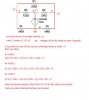
1. I know that The current splits through the two 500ohm resistors is -0.5mA
2. I want the current going through R1 to get the voltage. I know the current the current going into the node N1 will split between R3 and R2.
Here I get stuck.
I know that I can take 0.5mA from the current going through R3 and I can take 0.5mA from the current through R2 to get the two currents going into R1.
I can then take them away from each other and multiply by R1 to get the voltage across R1.
BUT, what's the current's flowing through R3 and R2? Do I use current divider? ... I keep getting it wrong.
Thanks for the help again Mike! (even though this is separate from the Logic stuff!)
Thanks a LOT! I do find it a little hard to see how R1 is in parallel with R4 and R5, though I think if I look at it a little longer I shall get it.
Hello there,
It always helps to look for symmetricalness in a circuit and in this circuit we find just that with R4 being equal to R5. This leads to quick simplifications. Since these simplifications are best shown graphically, i've included a diagram.
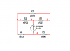
Referring to the diagram, in Fig 1 we have the original circuit. If we look carefully we can see that R1 is in parallel with two resistors R4 and R5 which are both the same values (500 ohms each). This means that if we were to divide R1 into two pieces R1a and R1b that were exactly one half the original value then the center tap would have the same potential as the center tap of the two 500 ohm resistors, and that means we can short the two center taps together and end up with the same circuit. This is the circuit shown in Fig 2.
Note that with this seemingly small transformation we have now greatly simplified the circuit, because now R1a is in parallel with R4 and R1b is in parallel with R5 and this means we can calculate a new value for both of these and reduce the circuit to four resistors This is shown in Fig 3.
Now we note that both sides of the circuit each have two resistors in series, so we can again simplify by calculating their combined series resistance on each side. This circuit is shown in Fig 4.
Finally we see that this circuit has been reduced to two branches where we can use simple current division to calculate the two branch currents.
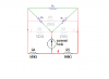
Now knowing both branch currents we can refer back to the original circuit (Fig 5 with blue arrowheads showing the branch currents) and use simple Ohms Law to calculate the voltage across R3 and across R2, then subtract those two to get the final voltage across R1.
Note that if R4 and R5 where not the same we would have had to divide R1 up differently.
The technique MrAL has shown here doesn't work in general. Just because R4 and R5 are equal in value, and their series combination is in parallel with R1 doesn't mean that you can split R1 into two equal value resistors (each equal to R1/2) and connect their junction to the junction of R4 and R5, and expect ALL the circuit properties to remain unchanged. Whether or not this is true depends on the rest of the circuit.
This only works because of a couple of special circumstances in this circuit:
1) The problem asks for the DIFFERENCE between V(N2) and V(N3); that DIFFERENCE is unchanged by the change you made going from your Fig 1 to your Fig 2. The individual voltages at node 2 and node 3 are different in the two cases, however.
2) It's only because of one additional special circumstance that the DIFFERENCE is unchanged by the connection you made from the junction of R1a and R1b to the junction of R4 and R5. That circumstance is the fact that node 1 is energized by a current source (which has theoretically an infinite source impedance). If node 1 is driven by a voltage source, or if there were another resistance from node 1 to node 4 causing the equivalent source to have less than infinite output resistance, then the DIFFERENCE between V(N2) and V(N3) would not be the same in Fig 1 and Fig 2.
3)Generally, making the connection between the junction of R1a and R1b and the junction of R4 and R5 is only permissible (causes no change in ANY of the circuit behavior) if the voltage at those two junctions is identical BEFORE you connect them.
Hello Electrician,
Actually, this is a general topology transformation that works in any circuit...
In the original circuit, replace the 1 mA current source with a 1 volt voltage source. Now the voltage across R1 is 64.51613 millivolts.
What do you get using your transformations? The current in R3a is now 4.44444 mA, which, if the same current flows in the original R3 means that there is a voltage drop of 125/225 = .55555 volts. The current in R2a is now 2.8571 mA, which, if the same current flows in the original R2 means that the drop across R2 is .7142857 volts. The difference is 158.73 millivolts.
This is not the same as in the pre-transformation circuit.
Apparently, this transformation doesn't work (get the correct answer) for just any circuit.
If you are trying to tell me that superposition is not a good thing you are going to have a very hard time convincing me.
Also note that i am not trying to force you to do it this way or that way, do it however you feel more comfortable with.
That's not entirely true however. If you are going to criticize superposition "because it usually involves more math because you have to solve the circuit repeatedly for each source" that's not a good enough argument because the resulting circuits are often greatly simplified (as in the example i did previously where we reduced the circuit into simple voltage dividers). Thus, if you are going to say there are more circuits to solve then you also have to say that those circuits are simpler too.Quite the contrary; I said "...superposition is a method that is generally applicable to any circuit." My only criticism of superposition is that it usually involves more math because you have to solve the circuit repeatedly for each source. But, what is good about it is that it always gives correct answers, no matter whether the circuit is driven by current sources or voltage sources.
Yes, after careful consideration i have to agree, and am in favor of abandoning the idea in order to avoid confusion. I went through the trouble of proving that the method will be more difficult to apply for some circuits, and for some circuits it may not be possible to meet the requirements of the node. It's a bit hard to determine if the requirements of the node are met or not sometimes, so i think it is best avoided pending further investigation.You didn't point out that the transformation you used is not generally applicable, and a reader of the forum who didn't realize that, might try to use the method with another circuit which didn't use a current source and get a wrong result. In fact, the OP commented in post #7, "I do find it a little hard to see how R1 is in parallel with R4 and R5..."
Hello there,
Referring to the diagram, in Fig 1 we have the original circuit. If we look carefully we can see that R1 is in parallel with two resistors R4 and R5 which are both the same values (500 ohms each). This means that if we were to divide R1 into two pieces R1a and R1b that were exactly one half the original value then the center tap would have the same potential as the center tap of the two 500 ohm resistors, and that means we can short the two center taps together and end up with the same circuit. .
dear MrAl,
just looked at the way you solved it, as you mentioned dividing R1 into two to make it in parellel to R4 & R5 will not work in this case. after divide it into two & beore connecting, if you note the direction of voltages R1a & R1b will have a voltage drop in the same direction but R4 & R5 will be in opposite. the junction will not have the same potential to connect them to resolve the problem.
if you have doubt work out in both methodss & check the answeres.