Continue to Site

Welcome to our site!

Electro Tech is an online community (with over 170,000 members) who enjoy talking about and building electronic circuits, projects and gadgets. To participate you need to register. Registration is free. Click here to register now.

  • Welcome to our site! Electro Tech is an online community (with over 170,000 members) who enjoy talking about and building electronic circuits, projects and gadgets. To participate you need to register. Registration is free. Click here to register now.

Need help with that cranky motor controller again ..... Sorry

ramblin

New Member
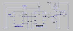
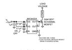
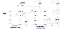
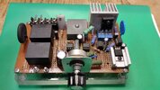
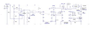
I got some really great advice here on building my budget motor controller. It worked , although not perfectly with old, obsolete parts. So it became time to put everything nicely on a board with components you could actually find and I'm back to about 90% working again. On my scope I get a "nice" square wave (4.2vdc) at the opto output / gate driver input with full duty cycle control. At the gate drive output .... not so much. Do I understand correctly that its difficult to get an output on my scope (due to going - neg or to fast or something)?? Surprisingly I get 100+ vdc testing a hand drill or light bulb at the mosfet. But I get no duty cycle control. Everything I tried gets full power. Maybe someone can take a look and tell me where I went wrong again. I believe I have everything correct to this drawing with updated components.
 

Attachments

  • driver-mosfet.JPG
    driver-mosfet.JPG
    96.6 KB · Views: 99
You appear to have an extra 0.1uF cap between VCC / VS power and OUT on the gate driver?

That will be causing problems, taking a lot of the gate drive current.
 
You appear to have an extra 0.1uF cap between VCC / VS power and OUT on the gate driver?

That will be causing problems, taking a lot of the gate drive current.
Not to mention another random 0.1uF between the two power pins? - but at least theat will have no detrimental effect :D

I presume the spurious one connected to OUT should be a decoupler, going to Gnd?.
 
OK, I see what you mean about vcc to vcc. It appeared to me they went that way. I couldn't figure out what that would do. Now I know . Thanks. Also I need to get rid of the vcc to out ? That was from the 1st build. Man... I messed up.
 
Just a nit:
Don't draw schematics with a wire going across half the page to a ground symbol, as that makes the schematic hard to read.
Just put the ground symbol close to component being grounded.
Ground symbols can be put anywhere, they don't have to all be at the bottom of the page.
 
crutschow, Glad you commented here since my PWM is your comparator circuit from 2017. That circuit works flawlessly for me. Thank you. Others here have helped me add the drive section. I seem to be good up to the Opto. At the opto output I have a nice square wave 3.5 vdc to 4.9vdc @ 3-4ua depending on the duty cycle. I have the gate driver and a fet on a breadboard exactly as in this pic. The issue is the gate driver output. With no power connected to VCC on the gate driver I can see a very low power square wave on my scope at out and Gnd. @ about 2-2.2vdc. If I put 12vdc to VCC my square wave goes away. I have 12vdc now but just 12vdc. No duty cycle. (no sq. wave). Now if I use a veritable power source and slowly add 1-2vdc I get a nice sharp, clean square wave at the out and gnd. again, still not enough to drive a fet. As I increase voltage to 3-4 vdc at VCC the wave just decreases to nothing by 5vdc. Just a horizontal line. I get what ever I add at out and gnd, but no pulsing. This is the best I can explain it. My PWM output is 0 -12vdc @ 11ua. Output at the opto is 3-4.9vdc @3-4ua. Just doesn't seem like enough. What am I missing here ?
 

Attachments

  • breadboard.JPG
    breadboard.JPG
    72.1 KB · Views: 81
OK guys, I have got my circuit working really well driving a cordless drill with separate 12vdc power supply. Seems my previous issues stem from me trying to upgrade my obsolete fairchild2631 opto to an available VO2631. For reasons I do not understand I could not make a gate driver work with these. It works well now with the old opto throughout the duty cycle wired exactly as shown in my drawing. The fet is the only component left on a breadboard and its getting pretty warm without a heatsink. I have a nice heatsink on the mainboard for it. Is there anything else I should do / add or change before I try my 100vdc power supply and motor ??? Everything I accomplished I learned here with the help of many of you, including reading a lot of old threads on this. Thank you! Please advise me of anything further I need to do.
 

Attachments

  • latest.JPG
    latest.JPG
    105.5 KB · Views: 80
You have taken out the 0.1uF decoupling cap, as well as the stray caps - I'd suggest adding one or two 0.1uF back across power (VCC and GND) on the gate driver IC, to help with the fast pulses.

That may even allow the MOSFET to run slightly cooler?
 
OK, I have a 100uf there now. Did you see it ?
Electrolytic caps are not all that good at high frequencies; they are good for moderate speed power buffering, but you need small plastic film or ceramic caps across power and ground at each IC that will be causing high frequency current fluctuations.

They provide both the fast response that electrolytics cannot, and avoid the inductive reactance of long power or ground traces - a good high frequency cap can be partially isolated simply by long connections.

More info:
 
Electrolytic caps are not all that good at high frequencies; they are good for moderate speed power buffering, but you need small plastic film or ceramic caps across power and ground at each IC that will be causing high frequency current fluctuations.
You posted this at the right time as I'm studying about decoupling caps now because I'm wondering why I need 0.1uf caps when I have a 100uf there. Now I understand why. So my next question is do I need the 100uf there at all If I add (2) 0.1uf caps ? Some one may have just told me to put one there.
 
So my next question is do I need the 100uf there at all If I add (2) 0.1uf caps ?
To even out the current drawn from the upstream supply, and again bypass some of the connection resistance from that.

Think of is as like a local reservoir cap, to reduce current ripple on the external wiring.
 
You posted this at the right time as I'm studying about decoupling caps now because I'm wondering why I need 0.1uf caps when I have a 100uf there. Now I understand why. So my next question is do I need the 100uf there at all If I add (2) 0.1uf caps ? Some one may have just told me to put one there.
A big capacitor for low frequency decoupling, and a small capacitor for high frequency decoupling - hence two wildly different values.
 
I am very happy to report my controller works even better than I expected. I added in the recommended caps and ran it for over an hour + on the machine I made it for. Speed control was smooth and with full range. The mosfet never got beyond "warm to touch" even after many shutdowns and startups, many speed changes and a while at about 50% duty cycle. In the past this machine using a variac would draw about 3-4 amps depending on the load and considerably more on startup. I didn't check today but would expect it to be less now. Quite honestly, I expected it to be much more finicky with the cheap, limited amount of components. I don't think I will have any problems since most of the time it works in the range I tested it in today. Special thanks to crutschow for providing the PWM circuit and rjenkinsgb, nigel goodwin and danadak for all there knowledge and walking me thru this project. I am so happy with the way it turned out I want to post a video, but I will be content with just posting the circuit and a pic of it completed !
 

Attachments

  • top .jpg
    top .jpg
    1.5 MB · Views: 64
  • final.JPG
    final.JPG
    107.4 KB · Views: 57

Latest threads

New Articles From Microcontroller Tips

Back
Top