Continue to Site

Welcome to our site!

Electro Tech is an online community (with over 170,000 members) who enjoy talking about and building electronic circuits, projects and gadgets. To participate you need to register. Registration is free. Click here to register now.

  • Welcome to our site! Electro Tech is an online community (with over 170,000 members) who enjoy talking about and building electronic circuits, projects and gadgets. To participate you need to register. Registration is free. Click here to register now.

Need help with my project (PC PS powered omron timers)

Status
Not open for further replies.

dalmatoid

New Member
Hey peeps

I really need some help. Im basically a noob when it come to electronics but I really enjoy making my own stuff and learning along the way.

I'm building a timer box from my high pressure aeroponic system. So this is the basic idea:

My aero setup has 8 12v solenoids, these solenoids must fire all at the same time. They will be powered by an omron timer. The solenoids will shoot pressurized mist for 1 sec every 3 minutes during the "day" interval and for 1 sec every 5 minutes during the "night" interval. The plants roots need less mist during the night cycle so thats why the longer pause duration is used at night, in order to avoid over saturating the roots. (these on and off times for the day and night intervals are just a starting point, more adjustments will be needed based on plant needs)

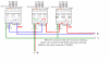
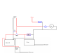
A PC power supply will be used to power three omron h5cx timers. Each timer is set to work in twin timer mode. The main timer will switch the other two timers on and off. The main timer will be set to 12 hours "day" and 12 hours "night", during the 12 hours of day the main timer will power on the second omron which will be set to 1 sec ON and 180 sec OFF, during the night the main timer will power on the third omron which will be set to 1 sec ON and 300 sec OFF.

Here is a pic of the diagram I made.

**broken link removed**

The solenoids are 12V 0.5Ma each...so 0.5*8 solenoids equals 4A total for the solenoids. My PC PS can handle 16A at 12V.

When I figure everything out I will build a box that will hold all the components.

Here are my questions:

I know I need to use some diodes at the exit lines, just not sure how strong they must be?

A friend suggested I use a relay to avoid having the higher amperage go through the Omrons, any thoughts on this?

In case of a power outage my plants can seriously suffer if the roots are not getting misted at the required intervals. I plan on using a car battery as a back up power source in case the main power goes out. What would be the best way of incorporating a car battery as a back up? Arent they at 15V when full? Would I connect the battery lines directly to the lines exiting the PS?

Also if you have any comments or suggestions please let me know.

I appreciate any help. Thanks :)
 
The solenoids are 12V 0.5A each...so 0.5*8 solenoids equals 4A total for the solenoids. My PC PS can handle 16A at 12V.

When I figure everything out I will build a box that will hold all the components.

Here are my questions:

I know I need to use some diodes at the exit lines, just not sure how strong they must be?
I would use 1N4001, they are rated at 1Amp 50Vrev


A friend suggested I use a relay to avoid having the higher amperage go through the Omrons, any thoughts on this?
This depends on the Omron contact rating, if its less than say 5Amps, I would recommend an external 12Vdc relay rated at least 10Amps, choose a contact change over type.

In case of a power outage my plants can seriously suffer if the roots are not getting misted at the required intervals. I plan on using a car battery as a back up power source in case the main power goes out. What would be the best way of incorporating a car battery as a back up?

Arent they at 15V when full? Would I connect the battery lines directly to the lines exiting the PS?
I would say they are approx 14V while being charged and will fall back to approx 12.4V after an hour.
If you choose a change over relay, you could wire it so when mains power is available the relay contacts select the 12V from the PC psu and when that is OFF, the relay will select the 12V lead acid battery.

hi,
The battery will have to be kept in a charged condition by using a suitable 'float' charging system ie: dont continuously over charge.

Post details of your Omron timer.

Eric
 
hi,
The battery will have to be kept in a charged condition by using a suitable 'float' charging system ie: dont continuously over charge.

Post details of your Omron timer.

Eric

Thanks for the reply :)

The timers are Omron H5CX-AD

here is a link for their data sheet:

https://www.electro-tech-online.com/custompdfs/2013/06/h5cx_dsheet_csm100.pdf

On page 4 and 5 are the specifications of the timers. I look at all the specs but I couldnt really figure out how much amperage they can handle...

I will have to look into this "float" charging system for the battery, thx :)
 
If I use a change over relay, how fast is it when it switches power from main source to battery source? Could there be a short drop in power causing the timers to reset?
 
If I use a change over relay, how fast is it when it switches power from main source to battery source? Could there be a short drop in power causing the timers to reset?

hi,
From the datasheet it appears the Omron contact rating is far less than 4Amps at 12Vdc, so I would suggest an external 12V, 10Amp SPCO [single pole change over]relay.

To prevent the Timers from resetting you could use a high value capacitor to supply the Timers during the relay switch over period.

Can you confirm that the Omron is being powered by the 12V from the PC psu.??

E

EDIT:
Have you read the warning on page #8 of the datasheet regarding pins #1 and #6 being linked internally.?
 
Last edited:
hi,
From the datasheet it appears the Omron contact rating is far less than 4Amps at 12Vdc, so I would suggest an external 12V, 10Amp SPCO [single pole change over]relay.

To prevent the Timers from resetting you could use a high value capacitor to supply the Timers during the relay switch over period.

Can you confirm that the Omron is being powered by the 12V from the PC psu.??

E

EDIT:
Have you read the warning on page #8 of the datasheet regarding pins #1 and #6 being linked internally.?

I'm in the process of building a power supply from a new PC psu. My friend is helping me do this and we will test the 12V line with a multimeter to confirm that the psu will supply the Omrons with the adequate voltage. I have been doing a lot of research on how to convert PC psu's to 12V power supplies and I think I can manage the task.

I have read the warning and I understand that #1 and #6 are linked but I dont understand how that affects me and how it would influence my design. I did a test with the timers using the above diagram and everything worked fine. I just have to bridge contacts #6 and #8 for the timers to start the twin timers when they get power, otherwise they will just turn on but wont count.
**broken link removed**

I will look into high value capacitors for the relay switch period.

Eric thx for the advice :)
 
hi,

If your PC psu conversion is an ATX type , it should already be able to supply +12V at a reasonable amperage.

If you get stuck on the external relay and battery switching, just ask.
 
yeah the PC psu is an ATX. I might need some help with the battery switching. I will look into it and let you know, thx. :)
 
hey Eric, could I use something like this to keep the battery in a float charged state: **broken link removed**

Or is there a better option?
 
Here is a diagram I made with the help of my friend. Does this look ok?

**broken link removed**

What should the capacitor capacitance be? Is it even in the right place? (we assumed it should be a polarized capacitor, bc we think the capacitance should be rather large)

Should we add anymore diodes to prevent any unwanted current between the supplies?

Can we use the same value relays (10A 12V)?

Are there any other safety issues we should be aware of except the reversing the polarity which we know can make the capacitor explode :D ?

Thx :)
 
hi,
A quick look over your diagram, it is not correct.

I will look more carefully and come back with some questions.

Is the centre timer on your drawing the Master Omron.? and the two outer Timers Slaves.?

As you have drawn them, Slave B on the right is powered when the Master Omron relay is not energised and the left Slave A is energised when the master relay is closed.
Is this what you intended.???

You did say you had 8 Timers on the system
 
yes the center timer is the master timer that switches between 12h day and 12h night. The two outer timers are the day and night timers.

I dont quite understand what you mean. The master omron timer is always energized but it switches between outputs 4 and 5. Contact #4 powers the Slave A timer and contact #5 powers the Slave B timer.

I dont have 8 timers but rather 8 solenoids that will be controlled by the timers.

hi,

OK, when you said 8 I read it as 8 Timers, sorry.

Those diodes to the right side relay serve no purpose as shown on your present drawing.?

As you say the Master switches power to either Slave A or Slave B, so there is no 'sneak' path for the diodes to block.?

I am making a new drawing for the battery and switch over relay, post later.

Where on you original drawings will the 8 solenoids be connected.?

E
 
I placed the diodes because when I did a test as shown in the photo I posted earlier there was power going the wrong way to the timer that should be turned off.

The solenoids will be connected just like they are in the previous diagram. On the original drawing they would be connected on the exit lines (on the right side upper side of the drawing)

hi,

Look at this marked up drawing, I do not see a current path that needs blocking diodes.?

The master relay contact selects Day or Night.

Assume Day is selected then the NIGHT Omron contacts back to its own inputs are Open, so no current path.

Likewise if the NIGHT is selected, the Day Omron contacts are Open.

Do you agree.?
 

Attachments

  • Omronwiring-1.png
    Omronwiring-1.png
    157.2 KB · Views: 299
hi,
This is how I would connect the battery and PSU etc.

E
 

Attachments

  • Image1.png
    Image1.png
    65.2 KB · Views: 265
I agree with you. I believe I figured out why we were getting some power going back...

When I was testing them I didnt use contact #4 on the slave omrons as the exit contacts, but rather contacts #5 which according to the diagram are Normally Open, and contacts #4 are Normally Closed. This could have been the reason some power was going back over.

If this is the case then using contacts #4 (as shown in the diagram) would eliminate the need for the diodes.
 
hi,
This is how I would connect the battery and PSU etc.

E

Thanks for the diagram. I will look at it in detail and try to make a prototype version to test out everything before I make a box for everything...

So would using a Battery Tender charger like I posted earlier be ok to use in my case?
 
Thanks for the diagram. I will look at it in detail and try to make a prototype version to test out everything before I make a box for everything...

So would using a Battery Tender charger like I posted earlier be ok to use in my case?

The Battery Tender looks OK, as always it would be wise to double check the state of the battery by using a meter, from time to time.

E,
 
Thx Eric for your help. Its much appreciated. I will start getting all the necessary parts so I can start building the timer box. I will post some updates of the project as it goes along.
 
Status
Not open for further replies.

Latest threads

Back
Top