Continue to Site

Welcome to our site!

Electro Tech is an online community (with over 170,000 members) who enjoy talking about and building electronic circuits, projects and gadgets. To participate you need to register. Registration is free. Click here to register now.

  • Welcome to our site! Electro Tech is an online community (with over 170,000 members) who enjoy talking about and building electronic circuits, projects and gadgets. To participate you need to register. Registration is free. Click here to register now.

Need help with a 555IC Circuit

Status
Not open for further replies.

gunlocators

New Member
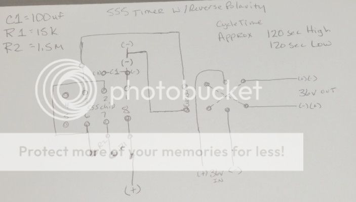
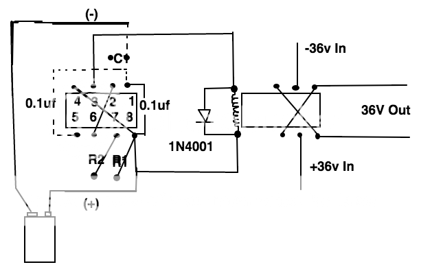
I have some 555 ICs and need to find a schematic for a circuit that will be on for 5 minutes and off for 5 minutes. Actually between 3-5 minutes is fine however the amount of time circuit is on should be very close if not the same as time off.

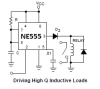
this will run a relay on and off I have the relay and the 555 probably most if not all the other components however when I google 5 minute circuit I did not find anything using a 555 IC any help is appreciated.
 
For a number of reasons I doubt you will get a 3 to 5 min symmetrical (50% duty cycle) from a 555 timer. If you read the data sheet it will tell you what a 555 timer can and cannot do. The formulas are provided for calculating On/Off timing. I would also suggest you **broken link removed**. To get the timing you want you would need what would be a perfect capacitor having zero leakage and that isn't going to happen. That is but one reason for the problems. There are also plenty of 555 timer calculators online that will do the math calculations for you. Anyway, I don't see you getting what you want in the 3 to 5 min range with a 555 timer. You may get one circuit to work, I just don't see it as an easy task for a 555.

While I have no clue what your project is there are Astable timing circuits that will work. That is what you want be it a 555 or other, it's called an Astable timing circuit and for your application with a 50% duty cycle. There are also a variety of "Repeat Cycle Timer Relays" as off the shelf solutions. A Google of Repeat Cycle Timer Relay will bring up dozens of hits.

Ron
 
This is what I went with for now and after 2 hours of letting it run it is consistant enough for now
555timer2min_zps55d67f16.jpg
 
Great, long as it works and meets your accuracy requirments. Must admit I had my doubts with those times of 3 to 5 min.

Ron
 
Your extremely simple circuit is missing diodes at the output of the 555 to protect against destruction from the inductance of the relay coil causing a very high voltage spike when it turns off.
Signetics invented the NE555 then Philips bought Signetics. The Philips applications note for the NE555 shows the important protection diodes.
Your circuit is also missing supply bypass capacitors of 0.1uF parallel with at least 1uF as mentioned in the datasheet for the LM555.
 

Attachments

  • 555 driving a relay coil.png
    555 driving a relay coil.png
    6.3 KB · Views: 200
Buy this TTL Cookbook it tells you all the things a 555 timer will do and circuits too.

There is also an online 555 timer simulator.

**broken link removed**
 
Last edited:
ScreenShot2014-12-20at93232PM_zps17b33d4a.png
Here is the revisions I am making c1 + to pin 2 and - to pin one wasn't clearly noted. Also thanks for link tp book ill buy it
 
Last edited:
Here is the revisions I am making c1 + to pin 3 and - to pin one wasnt clearly noted.
That is wrong. You never connect a capacitor from the output pin 3 to the ground pin 1.
The positive wire of C1 connects to pin 2, pin 6 and R2.
 
i too is connected i dint show the lines but this proto board i am using has condutors running off every 555 pin if that makes sense
 
If you building your circuit for a learning experience you won't be interested in this.

You can not build it for this price.

**broken link removed**


**broken link removed**
 
Status
Not open for further replies.

Latest threads

Back
Top