earckens
Member
I had posted this question in aother thread I had started about a soil moisture sensor module I am developping but it was probably not placed very well since no response came forward.
There are a few commercial sensors available using this technology (http://www.vegetronix.com/Products/VH400/, http://www.decagon.com/en/soils/volumetric-water-content-sensors/10hs-large-volume-vwc/, ..). Research on university level is being conducted on this sensor technology (**broken link removed** of Soil water sensors.pdf etc..). All advanced sensors for soil moisture measurement seem to use RF capacitance probes.
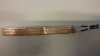
For this project I need to include a loss bridge. The purpose of this bridge is to measure variations in sensor capacitance. The sensor consists of a antenna inserted in soil, emitting a 100MHz signal obtained from a LTC6905 oscillator, and the measurement is done with a AD8307 logarithmic amplifier. The probe uses 2 insulated and waterproof parallel insulated copper strips; hence measurement is not done through electrical current but through electromagnetic fields.
I found a design used in a commercial moisture sensor measuring emitted power, and a design used for regular RF antenna or load balancing using a reference load.
For this project I presume both principles may be used, but I would like to receive your critical reviews on pro and con of each design principle.
The first attachment shows the design for the commercial unit where IC1=AD8307, IC2=LTC6905, R1&R2=470R, C1&C2=10nF

The values for the other, second, loss bridge are marked on the drawing.

What would/are be the pro and con for each design?
What would be recommended for a circuit used to measure the impedance (and hence emitted power) of a probe consisting of two copper strips (insulated and waterproof covered) 10cm long, a few mm wide and a few mm apart, inserted in soil.
There are a few commercial sensors available using this technology (http://www.vegetronix.com/Products/VH400/, http://www.decagon.com/en/soils/volumetric-water-content-sensors/10hs-large-volume-vwc/, ..). Research on university level is being conducted on this sensor technology (**broken link removed** of Soil water sensors.pdf etc..). All advanced sensors for soil moisture measurement seem to use RF capacitance probes.
For this project I need to include a loss bridge. The purpose of this bridge is to measure variations in sensor capacitance. The sensor consists of a antenna inserted in soil, emitting a 100MHz signal obtained from a LTC6905 oscillator, and the measurement is done with a AD8307 logarithmic amplifier. The probe uses 2 insulated and waterproof parallel insulated copper strips; hence measurement is not done through electrical current but through electromagnetic fields.
I found a design used in a commercial moisture sensor measuring emitted power, and a design used for regular RF antenna or load balancing using a reference load.
For this project I presume both principles may be used, but I would like to receive your critical reviews on pro and con of each design principle.
The first attachment shows the design for the commercial unit where IC1=AD8307, IC2=LTC6905, R1&R2=470R, C1&C2=10nF
The values for the other, second, loss bridge are marked on the drawing.
What would/are be the pro and con for each design?
What would be recommended for a circuit used to measure the impedance (and hence emitted power) of a probe consisting of two copper strips (insulated and waterproof covered) 10cm long, a few mm wide and a few mm apart, inserted in soil.

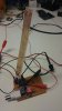
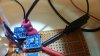
") : I used that circuit (#1) for testing today.
: I used that circuit (#1) for testing today.