Continue to Site

Welcome to our site!

Electro Tech is an online community (with over 170,000 members) who enjoy talking about and building electronic circuits, projects and gadgets. To participate you need to register. Registration is free. Click here to register now.

  • Welcome to our site! Electro Tech is an online community (with over 170,000 members) who enjoy talking about and building electronic circuits, projects and gadgets. To participate you need to register. Registration is free. Click here to register now.

Phase Controlled MOSFET Half-Bridge?

jschatzman

New Member
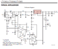
How to replace an SCR pre-regulator with a MOSFET circuit?

The datasheet for the LT1083/4/5 linear voltage regulator includes a schematic for a 7.5A regulator with SCR pre-regulator. I want to modify the circuit so that:
a) It uses a bridge rectifier so as to be suitable for a toroidal input transformer (trivial).
b) It uses MOSFET switches instead of SCRs for improved efficiency.

Point (b) seems more of a challenge. TI and AD sell ideal rectifier chips that make it easy to replace the diodes in a standard bridge rectifier with MOSFETS. However, those chips aren't designed to provide voltage control through varying the duty cycle, as the SCR pre-regulator does.

Is there a published circuit for this? Or a different MOSFET driver chip that supports duty cycle control? Or..?

Yes I am aware that the "modern" way to do this is with a switching regulator. However, I am looking for a solution that produces essentially zero RF EMI in any form. The SCR pre-regulator produces low frequency switching noise on the input but this can be filtered out.

Thanks for any ideas!
 

Attachments

  • Snap3.png
    Snap3.png
    76.9 KB · Views: 103
Solution
This is a 1994 doc before requirements were defined for active PFC on PSU's over 100W in recent years. It is also low EMI. Zero EMI is impossible ... maybe if you have military budgets. Please define all your specs, because you won't be able to use this method with FETs which will not meet your requirements.
Sorry, but your aim seems a bit confusing - you mention mosfet driver with "duty cycle" (pwm) but then say you don't want to use a switching regulator (pwm) ??


The pre-regulator is there for efficiency, so the linear stage dissipates minimal power regardless of the output voltage.

If you use anything other than a switching regulator, you will dissipate the same total heat between the two stages as a single regulator doing all the work.


If you do want to use an switch mode pre-regulator, then pretty much any buck regulator design would work in principle - just pick up the output voltage sense from the difference between the linear regulator input and output, rather than directly from the final output and ground, as with a single stage SMPSU.

eg. Something like one of these:


or these:


And using an either an optocoupler or a differential amp circuit for feedback between the linear reg input and output, rather than the voltage divider on the output,
 
This is a 1994 doc before requirements were defined for active PFC on PSU's over 100W in recent years. It is also low EMI. Zero EMI is impossible ... maybe if you have military budgets. Please define all your specs, because you won't be able to use this method with FETs which will not meet your requirements.
 
Solution
Thanks for the inputs.

I want to avoid using a flyback-type switching regulator - in particular, one that runs at high frequency (KHz-MHz). The reason for this is that my application is extremely sensitive to high frequency noise. Even the latest "low noise" switching regulators produce too much high frequency noise unless extreme precautions are taken. Adding enough filtering on the input and the output and providing enough shielding to prevent the high frequency leaking out of the PS is prohibitive. I do want to use a 60 Hz PWM pre-regulator, as in the AD tech note. Like I tried to explain, I am interested in swapping in MOSFETs for the SCRs.

I see Tony's note about PFC. That may turn out to be an issue for larger supplies but for now the 100W limit is fine.

I agree that zero EMI is impossible. Ideally, I don't want to be able to measure any EMI over 10 KHz. The usual peaks at multiples of the switching spead of a switcher power supply are not tolerable.
 
Last edited:
If you define the LDO input requirements, you can compartmentalize the problems and use any supply with Faraday cages, CM Pi Filters and anything else required. Don't complicate the design if you can apply isolation practices. With such a wide range of linear power, you might need water cooling with your approach. There are better ways if you can define specs for EMI.
 
Last edited:
I don't want to be able to measure any EMI over 10 KHz. The usual peaks at multiples of the switching spead of a switcher power supply are not tolerable.
Why? Almost everything you have has a switching power supply. Cell phone charger for an example.
I have worked with SCR regulators many years ago when they were popular. They trash the power line and need filtering. I would rather filter 100khz noise from the switcher than 120hz + harmonics.

I built a wide range linear high-power supply. To keep the linear part from overheating I got a transformer with many taps. There is a rotary switch in between the transformer and the diode-bridge. If I want 12V @ 10A then I set the switch to give me 15V from the transformer. (taps from 12 to 40V)
 
I built a wide range linear high-power supply. To keep the linear part from overheating I got a transformer with many taps. There is a rotary switch in between the transformer and the diode-bridge. If I want 12V @ 10A then I set the switch to give me 15V from the transformer. (taps from 12 to 40V)
I was expecting you to be using relays and auto switching :D
 
Many years ago we did build the circuit shown in the app note. Like yourself, we also attempted to use Mosfets instead of SCRs, but after a pair of attempts, went back to SCRs.

Why? Very simple: SCRs self commutation. They turn off once the current drops below the holding current. One only requires to trigger at the correct phase angle and the self commutation does the rest. Mosfets, on the other hand, requires a turn off signal synchronized with the current. Because the current’s zero cross varies with the load, one must sample the pulsing current.
Another failsafe SCR feature is that it cannot conduct reverse current, even if incorrectly triggered. A Mosfet which is accidentally turned on while the other is conducting (for whatever the reason, s**t happens) will result in a dead short across the transformer’s secondary winding.
Another SCR advantage is that you trigger it and forget, the Mosfet OTOH, requires continuous high side drive for the duration of the on period.
The result is that you require a more complex drive circuit. It can be done, but is more complex.

Now, the EMI is practically the same. The dI/dt is limited by the inductor. Whatever voltage ringing, can be quenched with a snubber.

The SCR has an additional advantage: for a particular die size and cost, the SCR’s fusing (I2t) capabilities are more rugged.

Most of the battery chargers we built 28 years ago are still operating in industrial environments.

Now, if you want to still use Mosfets, be my guest.
 

Latest threads

New Articles From Microcontroller Tips

Back
Top