Continue to Site

Welcome to our site!

Electro Tech is an online community (with over 170,000 members) who enjoy talking about and building electronic circuits, projects and gadgets. To participate you need to register. Registration is free. Click here to register now.

  • Welcome to our site! Electro Tech is an online community (with over 170,000 members) who enjoy talking about and building electronic circuits, projects and gadgets. To participate you need to register. Registration is free. Click here to register now.

IR triggered mousetrap help (repost)

Status
Not open for further replies.

ant9985

New Member
hi, iv got to do a project for my electronics course, so i thought id make a mouse trap, using two infrared beams to trigger the door closing mechanism.

it will be a long tube, with the beams at the back, and a trap door at the front held up by a small metal bar. An electro-magnet will be triggered on by the beams. This will pull the bar out of the door dropping it and trapping, hopefully, a mouse.

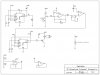
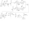
the electronics for one beam is taken from this site:

**broken link removed**

what i am going to do is: use those circuits. connect this monostable circuit:

http://images.google.co.uk/imgres?i...q=NE555+monostable+circuit&svnum=10&hl=en&lr=

to the output of the detector circuit, then connect a Miniature - Pull Action solenoid (like this: http://rswww.com/cgi-bin/bv/rswww/subRangeAction.do?cacheID=uknetscape)
for pulling the bar from the door.

I need some help with it all though.
Im worried about how to power it atm. it needs to be portable but i really dont know if 4x1.2v batteries, somone said i could use, will be enough for all this as the first link (IR circuits) indicates the use of a dual power supply (+12V, 0V, -12V) while Id have +4.8V and 0V from the battery only and also mine is powering a magnet.

another thing is, iv never used solenoids before, how do you connect them? and i cannot see anywhere on the monostable circuit that i can connect the output of the detector circuit too..

My last question is about the 2 beam settup. Will the 555timer be able to supply 2 IR diodes. i was told to look at the data sheet and see how much current the device can supply, and see how much an IR diode consumes, but when i looked, i cant remmeber the exact figures, but it made out that the 555 time wouldnt even be able to supply one diode. i know for a fact it can thought because iv build the ir circuit before with 1 IR diode and it worked fine. Can anyone help here? and tell me how to connect them and do ill need 2 phototransistors also wont i? how will i connect them and will they affect the circuit also

thnx very much for taking the time to read all this and any help u can provide is greatly appreciated :)
 
Before we address how to hook the three sections together it might be wise to review the power budget. You are interested in powering the device from batteries, so naturally we want the batteries to last as long as possible. I see an immediate problem with the design in that the IR beams are operating for the entire time the trap is switched on. Presumeably you would want it to operate for long periods of time, like a week or two. I note that the IR transmitter will consume approximately 29 mA at 12V. I get this by estimating that the peak current through the LED is about 45 mA using a 12V supply, and it is operating at a 50% duty cycle so its average current is 22.5 mA. Then I add the approximate current taken by the 555 alone which from the data sheet would be about 7 mA at 12V. Then I round it down to 29 mA. If you scale this circuit down to about 4.8 volts by using four 1.2V batteries, you will need to change the LED load resistor to maintain the peak LED current in order to maintain its intensity. The current drain of the 555 will come down to around 3 mA. So at 4.5 Volts, your total current drain just to transmit one IR beam will still be about 25 mA. Since you want two beams, you will be taking 50 mA at 4.8 volts. Now, to estimate how long the batteries might last, let's estimate that the IR receiver takes about 3 mA and the monostable takes about 2 mA (estimates using data sheets). So the system will take a total of about 55 mA before the mouse shows up.

Since you are using 1.2V batteries, I assume they are NiCd type but you don't say what size, so let's assume you are using C type NiCd cells. You might get about 1500 mAH from such cells, so I will use that for this estimate. So, if you divide 1500 by 55 then you get 27 hours. My opinion is that this is not enough for a mouse trap.

The alternatives for improving things are to
- reduce the intensity of the LED since your range from tx to rx is low and it is inside a tube with little interference. You could save a lot by doing this, perhaps more than 50%
- increase the batteries to D size. This might multiply the lifetime by 2 to 4 times.
- change the transmitter and receiver radically to pulse the IR led with a very very short duty cycle and at a lower rate. For example, if you used a second 555 timer to generate an ON/OFF pulse to enable or disable your first 555 then you could set it up to transmit a 5 KHz LED current that is on for,say, 1 mSec and then OFF for, say, 999 mSec. If you do this you will save a huge amount of power. This should work if we believe that the mouse will remain in the beam for at least one second. It will also be necessary to tell the receiver circuit when to pay attention to the beam and when not to. You can do this by wiring the output of the 1mSEc/999mSec pulse generator 555 over to the receiver and using an AND gate to only allow the receiver output to be valid/invalid during the 1mSec time. I'm sorry if this is hard to follow, so maybe I should prepare a simple schematic to show you the idea.

If you do the last item above, you will get much better lifetime from your batteries.

I'll address your questions on interconnection in a later post. By the way, the link for the solenoid device did not work for me.
 
I found another solenoid at Digikey that may be similar to what you were considering. Here's the link :
https://www.electro-tech-online.com/custompdfs/2006/04/L-75-120Tubular20Solenoid.pdf

If this is what you had in mind then we have another problem because this type needs a fair bit of power to make it work. For example, the intermittent version has a resistance of 3.3 ohms and needs 6 volts. That means it operates with a current of 1.8 amps. Our little Nicad batteries do have the capability of pushing this much current, but not when they are nearly dead. But it means that we need a current (or buffer) amplifier of some sort between the monostable output and the solenoid itself. We'll need to use a power transistor to drive the solenoid, one that is capable of the 2 or 3 amps that we need. This transistor will likely have a gain of less than 50, so we have to drive it with a base current of at least 40 mA which is within the capabilites of the 555 monostable. So we can wire the 555 monostable output through a base resistor to the power transistor.

Schematic needed here. Will provide later.
 
wow thats a big help! thnx a lot :D

those ideas to reduce power consumption are great, i dont think i have time to implement them all as my project should be in soon lol, but iv done a lot of the paper work and hopefully i wont have too many errors when i solder it together. but those ideas will go nicely in my improvements section. i like the last idea i would like to implement that if you could help me, im not so good at electronics as i should be, i dont think i learnt enough on my previous course for some reason.

anyway thnx very much :) i appreciate it

*Edit: well what ever solenoid u think will work best :)
 
The attachment is my first attempt at a schematic for this. Refer to it for this discussion.

I copied your transmitter without changes except it is powered from 4.8V VBAT. The receiver circuit has been modified to operate from a single power supply instead of +/-12V. The specific changes include the addition of R1. This provides a DC bias to the negative input that is referenced to VM which is a voltage that is halfway between 0 and VBAT. (please note that I made a minor mistake, R11 should be 10K). This VM is supplied by U6 which is an op amp configured to buffer the voltage generated at the junction of R11 and R12. We use an op amp this way to make sure that VM has a low equivalent output resistance. In this way, when we attach it to other circuits those circuits don't interact with each other depending on how much current they push or pull into VM.

The next change is that R1 and C3 are connected to VM instead of ground. This ensures that the quiescent bias point for U3 is 2.4V.

To connect the receiver output to your monostable, we first look at the polarities of the signal. When the IR beam is not broken by a mouse, you will be receiving a strong IR signal, so the 5KHz AC will pass to U2 and be amplified. In this case the output of U2 should have a large 5KHz AC output. D2 along with R1 and C3 work together as an AM detector. When there is a large AC output from U2, then the voltage on C3 will be below VM. When there is no IR beam being received, the voltage on C3 will be at VM. U3 is used as a comparator. When the IR beam is being received, the lower-than-VM voltage on C3 will be compared to the voltage that you adjusted at the slider of R8, which should be just a bit below VM or about 2.2 V. So when you receive the IR beam, the output of U3 will be high or near 4.8 volts. When the IR beam is broken, the output of U3 will go to ground. So this tells us the polarity of our output; high = no mouse, low=mouse in trap.

Since the trigger input of U4 is active low (when it goes low it triggers) we already have the correct output polarity from U3, so we can hook these directly together. So U3 output is connected directly to U4 trigger input.

More discussion in the next message.
 

Attachments

  • ir_mousetrap_schematic.jpg
    ir_mousetrap_schematic.jpg
    176.6 KB · Views: 226
My apologies for such a large graphic (I have to scroll left and right to see it all).

I have left the component values off intentionally to give you something to figure out.

The output of the monostable, U4 is fed directly to the solenoid driver Q2. I did this because I can see from the data sheet that U4 when triggered will put out a high and otherwise will remain low. The transistor is configured as a common emitter amplifier so it will turn on when the output of U4 is high and off otherwise which is what we want. You need to calculate the value of R9 as it is important to choose the right value here. You also need to choose an appropriate type of transistor for Q2. The most important parameter to watch for is the maximum collu77777777876yu (oops, my cat just walked across the keyboard) collector current and power disipation.

U5 is on the schematic because I didn't like the idea of using 741 op amps. So I chose a typical quad op amp device instead, where there are four op amps in one IC. In this case, the Vcc is at pin 4 and -VDD at pin 11 which is common to many types. U5 is a spare op amp so I've wired it up to not misbehave and oscillate. Your job is try and pick a better op amp from the many types available. The key parameter is to consider the dynamic range of the op amp output. It would be best if you chose a type that can swing fairly close to VBAT and GND. I've already picked my favorite and we'll see if we agree on this once you make your pick.
 
thnx very much :D, you've explained it very clearly, and obviously spent a lot of time on it, i appreciate it very much.

id just like to ask a few questions before i start working out the component values uv left out..

i can only see 1 IR diode/transistor. i really need 2 beams as it will pick up anything that moves if i dont.

C3 is the .047uF capacitor and the second R1 is 22k resistor from my circuit right? would 10k be ok for the first R1 resistor (the new one u added)?

thnx a lot :)
 
I forgot the other IR transmitter and receiver. The transmitter IC U1 should be able to drive two LEDs without much trouble in parallel, so the simplest way to have two transmitters is to add a second duplicate R7 and D1, also hooked up to U1 pin 3. Beware though, that this will force U1 to drive double the output current, which depends mostly on the value of the two resistors R7 and the new one. I recommend that you set the resistor values for a peak current of 20 mA instead of what was on that other circuit you are copying. They are using 45 mA per LED, probably to span a larger distance. In yours, start with a lower current and see if it works first.

For the second receiver you will be forced to duplicate quite a bit of circuitry, including all the circuits from Q1 and R3 all the way up to the output of U3. The second IR receiver needs its own sensor (Q1), amplifier (U2), detector and comparator (D2 and U3).

Once you have the second receiver, we can logically OR the two detector outputs together using an OR gate, or by using some diodes. I will leave this for you to figure out. The OR'd result will drive the TRIG input to U4.

Sorry about the two R1 labels. The first one should be roughly similar in value to R4 but this isn't critical. U2 is configured as an inverting amplifier and as such the junction at pin 6 is a summing junction. So, when we include the first R1 we are "adding" whatever voltage is at the other end of R1 to the voltage that is on the left side of R2. Since the left side of R2 has a DC blocking cap, only the AC voltage comes through there. So we are adding the AC from Q1 collector to the DC at the top of R1, which is VM. This is how we bias the op amp up to 2.4V for single supply operation.

R1 (the second one) and C3 are indeed 22K and 0.047 uF as you had before. The resistor and capacitor are chosen to have a time constant that is fast enough for the capacitor to discharge if the 5KHz being received and rectified at D2 disappears but not so fast that the circuit doesn't charge up C3 fully to begin with after a few cycles of 5KHz. Its an AM detector. You can study those more by looking up simple AM detectors used in AM radios.

We can review and give more advice once you have a schematic of the entire setup with component values as best you can work out. Don't show us little bits of the schematic, show us the whole thing, as context is often important to us.
 
thnx a lot for the help Ron. im not too sure about choosing the op-amps, and transistors. Its not that i cant be bothered, i really would love to be able to find datasheets for parts and be able to find the information i need from them. the thing is though i can never find the info off datasheets, perhaps they give the thing im looking for a different name or something. anyway, i attempted to work out resistors R7, R8 and R9 below:-

Calculating resistors R7+R8
Photodiode used: Fairchild QED233
Most performance parameters specified at 20 mA.
Voltage drop for photodiode at 20mA is typically = 1.2V
Timer used: LM555C
Output voltage drop(high): when 5V (close to 4.8V)@100mA the output voltage is 3.3V typically.
Resistance for this output = (5-3.3)/0.1 = 17 ohms
Output voltage when putting out 20mA = 5-(0.02 x 17) = 4.66V
But I will use 2 LEDs each taking 20mA so the output voltage will be: 5-(0.04x17) = 4.3V.
4.3-1.2=3.1V
3.1/20mA=155 ohms
so I will use a 150Ohm resistor before each photodiode.

Calculating resistor R18 (R9 in previous circuit)
Current needed: 40mA.
Output voltage drop(high): when 5V (close to 4.8V)@100mA the output voltage is 3.3V typically.
Resistance for this output = (5-3.3)/0.1 = 17 ohms
Output voltage when putting out 40mA = 5-(0.04 x 17) = 4.3V
4.3/40mA=107.4
so I will use a 100Ohm resistor for R9

so here is the circuit with values added, plz tell me if u think it needs altering, thnx :)
 

Attachments

  • complete circuit.JPG
    complete circuit.JPG
    213.3 KB · Views: 181
Those values seem OK. I do have a couple of other issues to mention though. You have included an OR function which in principle is correct, but in practice you have to watch out for polarities of inputs here. What I mean by this is that the output of each receiver is what I would call "active low". This means that when the mouse is breaking the beam, the receiver output will be a logic low, or in this case, 0 volts. When the IR beam is not broken, the output of the receiver will be high, or nearly 5 volts. The OR function that you have chosen is supposed to work with active high inputs, not active low inputs.

Let's review the OR gate for a second. When each input is low, the output of the gate is low. When one input OR the other input is high then the output of the gate will be high. If both inputs are high, then the output will also be high. This means that both IR beams would have to be broken for the output to go active. Is this what you intended? I thought you wanted it to work such that breaking either beam would sense the mouse is present.

When you are dealing with active low inputs (or as some might call it, negative logic), then you can get an OR function using an AND gate. Its easy to see how if you go through the basic logic. The AND gate will have a high output when one input AND the other input are high. This means that if either input is low, the output is low and when both inputs are low the output is also low. So in fact the AND gate performs an OR function for active low signals.

If you must use an OR gate there is another way to fix the problem so that you are indeed getting an OR function. All you need to do is to flip over both D3 and D4. This will flip the output polarity of the op amps following the diodes so that when IR beam is being received the op amp output will be low instead of high.

Another minor issue with the OR gate is that you don't specify a part number and you don't label the pins. Your schematic is incomplete in this regard and difficult to review. For example, if you are going to use a quad OR CMOS gate, and you showed the other three unconnected gates, we could tell you that their inputs must be grounded to avoid trouble.

When I first suggested a schematic I forgot to include the second IR transmitter and receiver, so you have drawn them in which is good. However, my original thought was to use a quad op amp (thats four op amps in one package) and I see that we now have a total of six op amps. In this case, we need to choose the actual part numbers. When we do, we will choose to have a quad op amp and a single op amp. In this case, we don't need U5. I only showed U5 before because it was an unused spare and we must always show how we have connected our unused spare gates and op amps.

What type of op amps shall we choose. We should go with ones that are rail-to-rail output but otherwise the circuit isn't too critical, so many types will work. Everyone has their favorites and there are several types that are available at low cost from many vendors. Do you have any opamps already that you want to use? What are their part numbers?
 
Looks like I'm a little late for this one, but here's another way you could do that. In this design, the IR beam is pulsing at some frequency, and picked up by a phototransistor (which is connected as a tuned amplifier). The R-C-D circuit at the collector acts as an AM detector, and the output is fed to the trigger of a monostable multivibrator. When the IR beam disappears, the MMV pulses the solenoid.

Doing it this way, you can turn down the power to the LED (with that variable resistor) to just a little more than it takes to prevent the thing from going off.


**broken link removed**
 
Hi i-build
Ant's circuit is transmitting with 5 KHz pulses, similar to your suggestion. That's a fairly low frequency and I guess it would be impractical to put the tuned circuit on the rx collector in that case. I'm guessing that your circuit would operate at a much higher frequency, like maybe 100KHz or so where the tuned circuit becomes more practical. Otherwise the ideas seem similar.
 
thnx for the replys :)

hmm this part here:
''When one input OR the other input is high then the output of the gate will be high. If both inputs are high, then the output will also be high. This means that both IR beams would have to be broken for the output to go active. Is this what you intended? I thought you wanted it to work such that breaking either beam would sense the mouse is present.''

i need the trap to close when both beams are cut as i dont want the device to trap anything like a small insect or something. I dont really understand what u mean here, as you said when the mouse is cutting the beam, the reciever output will be a logic low, so when both beams are broken the inputs to the OR gate will both be low and as u need high, it will output a low wont it?

i dont have any op amps, ill need to order the right ones, and yes that would be a good idea to use a quad op amp, but if theres 6 op amps in the circuit, we would need another quad op amp (dunno if u can get chips with 2 op amps in).

i_build_stuff: im gonna stick to the circuit iv already got, but thnx very much for the suggestion anyway :)
 
Status
Not open for further replies.

Latest threads

New Articles From Microcontroller Tips

Back
Top