Continue to Site

Welcome to our site!

Electro Tech is an online community (with over 170,000 members) who enjoy talking about and building electronic circuits, projects and gadgets. To participate you need to register. Registration is free. Click here to register now.

  • Welcome to our site! Electro Tech is an online community (with over 170,000 members) who enjoy talking about and building electronic circuits, projects and gadgets. To participate you need to register. Registration is free. Click here to register now.

interlocking switch

Status
Not open for further replies.
Yo Adrian...

If I may make a few suggestions as well.

You need to lock down what you really need and why? You as the one being tasked to perform the design must know all the details of what is needed, such as number of rooms, remote interfaces, how is communication performed. Interfaces to the remote reciever. Before you can really pursue this to an end, a set of requirements must be determined. At this point, it seems as those we are spinning our wheels.

Do not think I am getting annoyed or anything, as I and most others here like to help. It's what we do, but my request to you is this. Nail down what you actually need, perhaps start with a system level diagram. Make sure you have the overall picture in your mind and on paper.

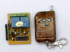
When you say to me that you are not sure how the remotes communicate I worry as it shows you do not yet have a good understanding of your own design. If you do not know, it is difficult to offer help.

Perhaps you should consider alternatives to your remote and look into wireless links designed for multi users. Or maybe even running wired multidrop serial comms.

What I am saying is that before we can help, you need a better idea of all the task and functions of your system. Take charge as Project Eng, set requirements, such as one switch for this, no that, etc.
Get what I am saying?
:)
 
OK, I've solved the problem as originally posted, but I do NOT suggest this as a final solution. ;) This so-called "solution" is only because I was fascinated by the relays-only idea. That said, this solution does use two diodes and one transistor.

I'm too tired to draw the whole thing out including the DPDT toggle switch wiring but the following should illustrate the idea. I'll try to get the DPDT wiring drawn out tomorrow if anyone is interested.

This solution requires three relays (SPST, although I have used DPDTs in testing and the schematic shows SPDTs), one DPDT toggle switch (centre-off), one 2N2222, a couple of signal diodes, two 100uF caps, and a handful of resistors and LEDs. It's pretty bulky and a little power-hungry for my taste but I've just carried the idea this far to see if I could come up with something which could do the job using the original relays-only requirement. Also, this is running on 12V, because that's what my relays need. :) And one thing you can't see yet is that it uses Ken's idea for the DPDT switch to discharge the caps (although that problem seems to also be partly solved by the centre-clear addition).

In the schematic shown the LED resistors are chosen for low-power 2mA LEDs with no thought yet given to differing red/green LED current requirements.

final_relay_solution-png.21409


Torben
 

Attachments

  • final_relay_solution.png
    final_relay_solution.png
    10.3 KB · Views: 222
Last edited:
Actually, my boss just want to know if such functions i asked before can be done.

the remote control set i used to test is somehow like these:
 

Attachments

  • 2jkg-2.jpg
    2jkg-2.jpg
    24.2 KB · Views: 132
  • 2u.gif
    2u.gif
    17.3 KB · Views: 127
Ugh Torben, you must be using real high res settings. Your image sends all your text way off my screen. My eyesight is not so good so I stick to 1152x864. Why two leds per trig branch? Does that setup up currents or something for the cap?
I still like my circuit as it only needs 10 parts, no relays. Not as bullet proof as yours though :)
 
Ugh Torben, you must be using real high res settings. Your image sends all your text way off my screen. My eyesight is not so good so I stick to 1152x864.

Sorry about the resolution thing. My laptop's native resolution is 1680x1050. I hoped that image would be relatively small but I guess not.

Why two leds per trig branch? Does that setup up currents or something for the cap?

Nope, just one LED for inside the door and one LED for outside the door.

I still like my circuit as it only needs 10 parts, no relays. Not as bullet proof as yours though :)

Well, like I said I don't think this is a good final solution. I just wanted to see if I could figure out a way to solve the problem as originally presented. Now I can free my mind of that particular problem and move on to more realistic solutions, which will probably look more like yours. :)


Torben
 
Actually, my boss just want to know if such functions i asked before can be done.

the remote control set i used to test is somehow like these:

From the pics, I do not see how you could ID one remote from another. Do you have link for remote?
 
From the pics, I do not see how you could ID one remote from another. Do you have link for remote?

Back to practical questions. :) Good idea. I'm off to bed though. Night all!


Torben
 
sorry, what do you mean ID? I can hardly find the datasheet of that remote, i will keep finding.

I mean identification. How will you know one remote from another? If they all put out same frequency and codes, it will be hard to know which room is requesting service. See what I mean?
 
Last edited:
Ugh Torben, you must be using real high res settings. Your image sends all your text way off my screen. My eyesight is not so good so I stick to 1152x864.

You could alter the DPI setting to make system fonts larger, rather than using a lower resolution.
 

Attachments

  • DPI Setting.gif
    DPI Setting.gif
    92.5 KB · Views: 131
You could alter the DPI setting to make system fonts larger, rather than using a lower resolution.

Yeah, that's what I do. Makes the fonts look smoother too.


Torben
 
Thanks, I will try that.
 
I mean identification. How will you know one remote from another? If they all put out same frequency and codes, it will be hard to know which room is requesting service. See what I mean?

I think the range of the remote control should be selected not to be so large, so that we can arrange the remote control sets as the picture shown. I think the signal will not overlape. How about your suggestion?
 

Attachments

  • rooms.JPG
    rooms.JPG
    23.1 KB · Views: 113
Hi,

Bit tired ....
and pondered this so long that i'm not sure ive got it right ....

Also havent included the LED indication, another set of three probably.

As shown, should be minimum battery draw,
and quenching of the cap thats not in use,
so that even mistaken switching between positions should not be a problem.

John

******************

rotary-switch-jpg.21447
 

Attachments

  • Rotary switch.jpg
    Rotary switch.jpg
    33 KB · Views: 218
Last edited:
I think the range of the remote control should be selected not to be so large, so that we can arrange the remote control sets as the picture shown. I think the signal will not overlape. How about your suggestion?

Ok here are a few questions.

I took your image and modified it. I see what your thinking here but here is the thing. With limited range Transmit, the receiver would have to be close enough for coverage. Look at my image, with coverage for Area 1, then Area 2 would not be able to transmit to RX1. Only way I see around this is multiple receive units, is that your plan?
Also is the reciever able to receive multiple frequencies? Say room 1-3 frequency?
 

Attachments

  • roomcoverage.gif
    roomcoverage.gif
    19.8 KB · Views: 128
Adrian, I don't think you ever answered my question about how far the devices must be able to send.

Will there be a portable unit in each room which must reach only to a display unit on the door, or must all rooms be able to send individual signals to a central location somewhere in the hotel?


Torben
 
Going by Adrians previous image. It would appear that there is a seperate remote for each room, ie. room 1 has freq 1, room 2 uses freq 2 etc. The drawing provided by Adrian would also imply a multi channel RX which I questioned. Adrian also assumed he could use redundant remote frequencies which would not interfere based on distance from TX room 1 with TX room 4, which would force multi RX units to maintain full floor coverage.
IMHO this plan is not to workable as is.
Perhaps the wireless idea be thrown out in lieu of a wired approach like a multi addressable 2 wire bus where the wires are ran under carpet or something.
I dunno...
 
Ok here are a few questions.

I took your image and modified it. I see what your thinking here but here is the thing. With limited range Transmit, the receiver would have to be close enough for coverage. Look at my image, with coverage for Area 1, then Area 2 would not be able to transmit to RX1. Only way I see around this is multiple receive units, is that your plan?
Also is the reciever able to receive multiple frequencies? Say room 1-3 frequency?

Each room have it own set of remote control and reciever. room 1-3 are independent. The frequency used in room1 will not be used in room2,3 and vice versa.
 
Adrian, I don't think you ever answered my question about how far the devices must be able to send.

Will there be a portable unit in each room which must reach only to a display unit on the door, or must all rooms be able to send individual signals to a central location somewhere in the hotel?


Torben

The receiver and remote control box should be fixed. otherwise why don't i used the original remote control directly(the problem will not exist)?
Not all rooms should sent the signal to central. The cleaner will check the outdoor LED indication. Just show the alarm outside the door is good enough.

The range of the signal to be send , i think 400 feet square is good enough.
 
Status
Not open for further replies.

Latest threads

Back
Top