Continue to Site

Welcome to our site!

Electro Tech is an online community (with over 170,000 members) who enjoy talking about and building electronic circuits, projects and gadgets. To participate you need to register. Registration is free. Click here to register now.

  • Welcome to our site! Electro Tech is an online community (with over 170,000 members) who enjoy talking about and building electronic circuits, projects and gadgets. To participate you need to register. Registration is free. Click here to register now.

helps needed

Status
Not open for further replies.

chinsoon

New Member
hello there....

I am working on my RF Remote Control.

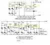
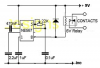
The circuit is done, but the problem is that when the transmitter is on, the response at the receiver is very small, and the pulse coming out from the NE567 IC has peak voltage of about 1mV.

As you can see, the output is suppose to trigger the transistor to turn the relay on, but the output is not sufficient to do so. So is it possible for me to just add in an op- amp and amplify the output? so that it is enough to trigger the transistor
 

Attachments

  • CD.JPG
    CD.JPG
    50.6 KB · Views: 251
Shouldn't there be a base resistor on the output BJT to reduce the load that needs to be driven? Add one before you try anything else.

But if you are going to add in an op-amp, you might as well just replace that BJT with a FET which requires much lower gate drive. Also, put a reverse-biased fast recovery (or Schotky) diode in parallel with the relay coils...or you will destroy the transistor there. Can the 6V relay run okay at 9V? You might need a current limiting resistor in series with the relay coils if it cannot.

I also suggest you put the relay coils on the high-side, and put the transistor on the low side (well it seems you already have PNP so that's a bit pointless), but if you replace the BJT with a MOSFET, use an NMOS and put it on the low-side with the relay coil on the high side. Works better than PMOS...but I guess this would reverse when the relay switches on. If you can't tolerate this, then just use a PMOS.
 
Last edited:
The output of the NE567 is a 100mA collector of an NPN transistor. It is probably broken because it tried to conduct more than 100mA into the base-emitter of your PNP transistor. It has nothing to turn off the PNP transistor.

You don't need the PNP transistor. Just connect the relay from pin 8 to the positive supply and add a reversed diode across it. I hope the PNP transistor didn't blow up the output of the NE567.
 
You don't need an op amp. You need to read the datasheet. Pin 8 is open collector, and can drive your relay directly. If you want to use the PNP as a relay driver, you need a pullup to +9V from pin 8 (~10k), and a resistor in series with the base (~1k). I don't think you need the 4.7uF cap on pin 8.
Your relay coil needs a diode in parallel with the coil to prevent excessive flyback voltage. A 1N4148 should work, unless your relay coil current is more than 100mA or so. If it is more than 100mA, use a 1N4001.
 
audioguru said:
The output of the NE567 is a 100mA collector of an NPN transistor. It is probably broken because it tried to conduct more than 100mA into the base-emitter of your PNP transistor. It has nothing to turn off the PNP transistor.

You don't need the PNP transistor. Just connect the relay from pin 8 to the positive supply and add a reversed diode across it. I hope the PNP transistor didn't blow up the output of the NE567.

I've tried to measure the output current as you said, but it seems like the current is less than 1mA. I've also changed another new NE567... and the result is still the same. so even if i connect the pin8 to the relay as you said, can it still trigger the relay at current of about 0.23mA???
 
How do u trigger the relay at 0.23 mA?
How do u measure the output current?
Just like what audioguru said, I have a cheap receiver which is using 567 as well, it works okay.
 
This is how a relay should be connected to an NE567:
 

Attachments

  • NE567.PNG
    NE567.PNG
    28.4 KB · Views: 354
just to clarify as i am trying to figure out how the circuit works,

the circuit uses a crystal which is 27MHz, and i do not get any waveform at that frequency.. why is that so? is there something wrong with the construction? what i measured using the oscilloscope is a 580Hz waveform, which is the frequency of the 555 timer. then where is the 27MHz?

and how does the IFT work? ( i tried to look for info online, but couldnt find any on it..) can it be tuned?
 
chinsoon said:
the circuit uses a crystal which is 27MHz, and i do not get any waveform at that frequency.. why is that so?
The input capacitance of your 'scope is too high. Try it with a 10:1 'scope probe.

and how does the IFT work?
The IF transformer matches impedances like any other signal transformer. Usually they are tuned but this one doesn't have tuning capacitors shown.
 
audioguru said:
The IF transformer matches impedances like any other signal transformer. Usually they are tuned but this one doesn't have tuning capacitors shown.

But it will have them internally, it's just a standard little AM IF transformer.
 
audioguru said:
The IF transformer matches impedances like any other signal transformer. Usually they are tuned but this one doesn't have tuning capacitors shown.

the one i am using have a yellow portion ( i think its the color code for standard IFTs) as if it can be tuned.. i was wondering am i suppose to tune that as well.. other than the tuning capacitor...
 
The core of an old AM radio's IF transformer has a slot so a screwdriver can turn it to tune it so that its peak frequency is the same as the other IF transformers. This circuit has only one IFT so tuning it doesn't matter.

I looked in Google for a Denco IFT but they make dental tools now.
 
audioguru said:
I looked in Google for a Denco IFT but they make dental tools now.

Denco used to make a full range of coils for radios, back in the 60's and 70's, you could buy IF tranformers and full shortwave coil sets, RF and oscillator. But they disappeared years and years ago, I understand a full set of Denco coils for a shortwave receiver is now worth quite a bit?.
 
can someone explain this?

I really did alot of readings to find out about this circuit. and i really dont quite understand this:

the local oscillator on the receiver side is used to convert the received signal to a IF using the JFET is it? does anyone know who to calculate the frequency of that local oscillator? is it directly 27MHz since it is using a crystal? if so, then what is the use of the BJT and also the capacitors and resistors?

and then, i look through the datasheet of the ZN414 IC. it says that the frequency range (input) is only 0.15 to 3 MHz. so i measured the input and output of the IFT (input to the ZN414 IC) and i found that the frequency is about 580Hz (the frequency of the 555 timer at the transmitter). so why is it so???? so it goes back to my first question, what is the frequency of the oscillator circuit? and can all of these factors affect my output of the NE567. Now, i still cant get a output sufficient to turn on the relay. the output from the NE567 i got is about 3mV peak and i have no idea how can it be used to trigger the relay. Any idea? please let me know why.

thanks alot
 
Last edited:
chinsoon said:
can someone explain this?

I really did alot of readings to find out about this circuit. and i really dont quite understand this:

the local oscillator on the receiver side is used to convert the received signal to a IF using the JFET is it? does anyone know who to calculate the frequency of that local oscillator? is it directly 27MHz since it is using a crystal? if so, then what is the use of the BJT and also the capacitors and resistors?

I suggest you google "superhetrodyne radio", and learn about how a radio works. In the case of a superhet the local oscillator is either above or below the wanted signal, by the amount fo the IF transformer.

and then, i look through the datasheet of the ZN414 IC. it says that the frequency range (input) is only 0.15 to 3 MHz. so i measured the input and output of the IFT (input to the ZN414 IC) and i found that the frequency is about 580Hz (the frequency of the 555 timer at the transmitter). so why is it so???? so it goes back to my first question, what is the frequency of the oscillator circuit? and can all of these factors affect my output of the NE567. Now, i still cant get a output sufficient to turn on the relay. the output from the NE567 i got is about 3mV peak and i have no idea how can it be used to trigger the relay. Any idea? please let me know why.

You can't really easily measure the signal around the IF transformer, it will be VERY small - it will be 470KHz or so.
 
Nigel Goodwin said:
I suggest you google "superhetrodyne radio", and learn about how a radio works. In the case of a superhet the local oscillator is either above or below the wanted signal, by the amount fo the IF transformer.

of course i have tried.... and read some articles on it. and i know the stages of the superhet receiver... but when comes to circuit level, i cant really find much, especially calculations. at least i know what to expect when i troubleshoot....


Nigel Goodwin said:
You can't really easily measure the signal around the IF transformer, it will be VERY small - it will be 470KHz or so.

i measured some the voltage... its small like what you mentioned, but the frequency is not 470KHz... (or else i wont have headache..) the datasheet of the ZN414 says that the input range is 0.15MHz to 3MHz and i donno whether is the input within the range or not.

thanks
 
chinsoon said:
of course i have tried.... and read some articles on it. and i know the stages of the superhet receiver... but when comes to circuit level, i cant really find much, especially calculations. at least i know what to expect when i troubleshoot....


i measured some the voltage... its small like what you mentioned, but the frequency is not 470KHz... (or else i wont have headache..) the datasheet of the ZN414 says that the input range is 0.15MHz to 3MHz and i donno whether is the input within the range or not.

How did you measure it?, and what crystals were you using in both transmitter and receiver?.
 
i used the oscilloscope... and only saw a wave something like that...

even before the NE567... so the input and output of the NE567 i obtain is the same... just differ in magnitude...
 

Attachments

  • untitled.JPG
    untitled.JPG
    3.6 KB · Views: 128
Nigel Goodwin said:
That looks like bursts of RF, which is what you would expect from a crude AM transmitter. The NE567 needs to be tuned to the modulating frequency.

wow... now these i don really understand...

so how am i suppose to tune the NE567???

by the way, thanks alot for helping
 
Status
Not open for further replies.

Latest threads

New Articles From Microcontroller Tips

Back
Top