Continue to Site

Welcome to our site!

Electro Tech is an online community (with over 170,000 members) who enjoy talking about and building electronic circuits, projects and gadgets. To participate you need to register. Registration is free. Click here to register now.

  • Welcome to our site! Electro Tech is an online community (with over 170,000 members) who enjoy talking about and building electronic circuits, projects and gadgets. To participate you need to register. Registration is free. Click here to register now.

help understanding amplifier schematic

Status
Not open for further replies.

whiz115

Member
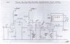
i got this design... and i need to ask why suppressor grid isn't connected
and if it is by mistake left outside...

second thing, i need to know if this amplifier needs split power supply or
if single is fine

also if somebody want to recomend any changes on component values it's ok...
 

Attachments

  • enisx-1.jpg
    enisx-1.jpg
    901.8 KB · Views: 350
In an EL84 the suppressor grid is internally connected to the cathode, there is not a separate connection.

A split supply is not needed.

The component values look OK, but the "tone control" circuit with the series pot and capacitor looks a bit odd, probably OK though.

JimB
 
The component values look OK, but the "tone control" circuit with the series pot and capacitor looks a bit odd, probably OK though.

JimB

i don't like it too... i think i'll transfer the volume control at the input...though i don't know what to do with the "tone"

also something else! the 270ohm/2W resistors are in parallel all together with the capacitor 25/50?
 
Last edited:
i don't like it too... i think i'll transfer the volume control at the input...though i don't know what to do with the "tone"

I'm presuming this is a guitar amp?, leave the controls where they are.

also something else! the 270ohm/2W resistors are in parallel all together with the capacitor 25/50?

Yes, all in parallel.

I would also suggest you make the anode loads of the triodes 1W resistors, they commonly fail otherwise.

Notice there's a capacitor added in pencil on the cathode of the second triode, you might make that switchable, giving a high and low gain setting.
 
I bet the distortion is pretty high since it has no negative feedback.
The output impedance is pretty high so the speaker has poor damping of its resonances.
 
I don't like that the last tube control grid is not ac coupled to the pots, with a fixed bias. The volume control changes the grid bias. This is not good. Right?

Edit:
Well maybe it does not effect the bias but it's good to not have any dc go through the pots if not needed. Noise may increase after a long time.

Then again, maybe I'm completely wrong and there is no dc just a charge so a cap would add nothing.

Comment please.
 
Last edited:
What language is this circuit written in?

It looks like Greek. Is it from Electronics Lab? This looks like the kind of thing they have over there.
 
guys please don't make me sad... what's wrong with the design?
i don't want any serious distortion! i want to be able to use it in all
circumstances, including just listening music.


@Hero999 yes it's Greek. No has nothing to do with electronics lab
btw why so much hate about that site? they are a useful comunity just like ours.
 
guys please don't make me sad... what's wrong with the design?
It uses vacuum tubes in an extremely simple and very old circuit:
1) It has very high distortion. Acid-rock is not music, it is distortion (fuzz) and noise.
2) It has low output power.
3) It wastes a lot of electrical power making heat.
4) Its low frequency response and high frequency response are poor because of its output transformer.
5) It has a high output impedance so it provides poor damping of the resonances of speakers.
6) Its performance keeps getting worse as the vacuum tubes wear out.

Many of the projects at Electronics-Lab don't work (except the ones I fixed). Some Greek projects have a horrible translation to English:
"When the tendency of catering is 56V then the attributed force of expense is 30 WRMS in charge 8." I think i know what it means.
 
I don't like that the last tube control grid is not ac coupled to the pots, with a fixed bias. The volume control changes the grid bias. This is not good. Right?

Edit:
Well maybe it does not effect the bias but it's good to not have any dc go through the pots if not needed. Noise may increase after a long time.

Then again, maybe I'm completely wrong and there is no dc just a charge so a cap would add nothing.

No, there's no DC - although it's not 'nice' relying on the grid 'bias' going to ground via two sliders - adding a 10meg resistor direct from grid to ground would be 'nicer', even though it would have no actual effect.
 
guys please don't make me sad... what's wrong with the design?
i don't want any serious distortion! i want to be able to use it in all
circumstances, including just listening music.

Why do you want to make such a design? - like I said before, it's probably a small cheap guitar amp, low performance, high distortion, poor frequency response - not nice for listening to music.
 
@Audioguru indeed the schematic is very old... looks like it is written
with typewriter and then corrected by hand.

it's nice that you're so direct person and you say things as they are...
but now i think you should help a bit because

1) i'm almost started building it and now i got disappointed with all these things you said.
2) I can't move on to a different design cuz i can only have the specific tubes available and i can't pay more for other tubes.

i know that you're going tol help!

thanks :D


@Nigel i was hopping it will be useful both for listening to music decent enough and as a small guitar amp... (i don't mind the output power at all...)


It uses vacuum tubes in an extremely simple and very old circuit:
1) It has very high distortion. Acid-rock is not music, it is distortion (fuzz) and noise.
2) It has low output power.
3) It wastes a lot of electrical power making heat.
4) Its low frequency response and high frequency response are poor because of its output transformer.
5) It has a high output impedance so it provides poor damping of the resonances of speakers.
6) Its performance keeps getting worse as the vacuum tubes wear out.
 
Last edited:
btw why so much hate about that site? they are a useful comunity just like ours.
Historically it was because many people here left Electronics Lab because one of the moderators was a Nazi who deleted anything he disagreed with even if it didn't violate the forum rules.


Luckily the Nazi moderator has been sacked it's not so bad any more.

However many people here are still not happy with Electronics Lab because it has many broken projects that people have fixed but the administrator shows no intention of applying these modifications to the circuits on the site. Although the people on the forum are generally quite helpful, a site with broken projects is not very helpful and only tarnishs the ameteur electronics community's reputation.
 
I made an amplifier with vacuum tubes in about 1961. It used a push-pull class AB circuit that cancelled even harmonics and extra wires on its output transformers (Williamson) for reduced odd harmonics. It sounded great for 1 year until I tested its output distortion to be about 20% at half its rated power. Then I replaced its tubes every 3 months because they were cheap.

In about 1964 I bought a solid-state FM stereo receiver. I still use it and it sounds almost perfect.
In about 1985 I bought another solid-state receiver. It is powerful and has extremely low distortion and excellent damping of the resonances of speakers.
I have made many IC amplifiers that sound great.

Tube amplifiers are crap. Today you can buy a very expensive amplifier with tubes on top. The amplifier is solid-state and the tubes are for show and are not part of the amplifier circuit.
 
οκ Hero999 i didn't knew these details about elecronics lab.

ok Audioguru... now could you please help me improve the diagram
i posted cuz this is my first tube amp which i really want to build and
i'm already having all the parts sittin' on my desk. :)

oh... it must remain single ended pls....
 
Last edited:
The cheap and simple tubes amplifier circuit cannot be improved.
The single-ended output produces even-harmonics distortion and the varying DC current from the output tube in the output transformer produces all-harmonics distortion.
The output transformer has phase-shift so negative feedback cannot be applied to reduce the distortion.
The output transformer has a high impedance feeding the speaker so the undamped resonances of the speaker will sound boomy and shrieky.

Make it like the schematic and keep its volume control at zero.
 
Status
Not open for further replies.

Latest threads

Back
Top