Continue to Site

Welcome to our site!

Electro Tech is an online community (with over 170,000 members) who enjoy talking about and building electronic circuits, projects and gadgets. To participate you need to register. Registration is free. Click here to register now.

  • Welcome to our site! Electro Tech is an online community (with over 170,000 members) who enjoy talking about and building electronic circuits, projects and gadgets. To participate you need to register. Registration is free. Click here to register now.

Help needed on designing a circuit for a digital clock (A level project)

Status
Not open for further replies.

MutantNoodles

New Member
I am doing Product Design as an A level at my school, and for my second project i decided to design a clock. However i didnt want to design any normal clock, because i did systems and control (circuitry and electicals) for my GCSE and i got an A* in it. I wanted to bring some of my electronics skills over into this project. But however i have a problem, i have no idea how to make a circuit for a digital clock, and especially not for the design i have in mind. This is the link for a picture of the idea seen head on : **broken link removed**
The idea is that instead of hands, or digits telling the time, i would use light. The outer 12 coloured rectangles are made out of acrylic and are 'embedded' in the wood, these indicate the hour individually by lighting up with LED's in the wood, eg in the picture it indicates that the hour hand is on or past 1 o'clock. The inner ring is made up of 60 LED's, each one representing its corresponding minute of each hour, the idea is to show the rough time on the minute hand, not to actually count up to what minute it is. E.g. 1:25
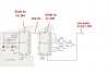
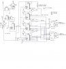
I have done some research on clock circuits and i am yet to find anything on a circuit like this, i am maybe thinking about using two decade counters somehow? Any help on what to do would be amazing. Thanks in advance :)
 
Last edited:
Be patient, sometimes it takes a week or so before someone with the relevant know-how replies and you only waited just over four hours.

If no one replies, post again with more information, just bumping a thread annoys people.:mad:

How's your programming?

You could use a microcontroller.

Unfortunately my programming isn't very good so I won't be able to assist you.:(
 
my programming is okay, for my gcse project i programmed a PIC chip for a car alarm, i managed to make the car alarm turn on and off via a key fob, when it turned on the alarm beeped twice and then the *alarm on* LED flashed every 2 seconds, and the alarm was tripped by 3 tilt sensors and reed switches on the car models doors, when the alarm went off, 9 LED's flashed together with the beeps from the sounder.
I was thinking about constucting two different circuits, one for the hours and one for the minutes, and then linking them somehow? But this is a whole new field for me, any help will be greatly appreciated.
 
I think using a microcontroller is the easiest and cheapest solution.

You can already program and you've had experience with PICs before so it should be easy.

You could use an LCD display and it will probably run off a couple of AA cells for years or you could use a mains adaptor and a large LED display.

I think you should do something original because you can buy clock modules pretty cheaply.
 
did you have a look at the picture of what i want it to look like? and read the description, its hard to explain, but it looks like the face of a normal clock, without the numbers, and the lines at each hour light up? and each minute is represented by an LED
 
No I didn't look at the picture because the link you posted directed me to a site with no picture which is probably another reason why no one responded.

Please post it as an attachment.
 
It's possible with 100 or so logic ICs or a microcontroller plus a couple of ICs which someone who's better at that kind of thing can probably help you with but you should wait a couple of days for them to respond.
 
if you want to use only counters, no PICs, then you need a good time base to get 1min pulse, then 8 no of 4017 can do what you want, also possible to have micro switches to set the current time.
if you wana do it by this way i can post you how it has to be wired.
 
As i said i am new to this feild, i have only had alot of experience in programming, and none with clocks.
I am getting quite close to the deadline, mbarazeen if you could help it would be great, is there no way to do it by battery, not by AC?
 
The problem with a battery is you'd need a very large battery to power the LEDs for a long length of time.

For example, to power two LEDs continuously for a year (consuming 10mA each, 20mA in total) you need a 0.02×24×365.25 = 175.32Ah 3V battery which will be about half the size of a car battery, a good quality rechargeable AA battery is just 2.7Ah at best.

If you don't want to use a huge battery, you need to run it off the mains. You don't need to worry about high voltage, just use a DC mains power supply plug aka wallwart.

Large numbers of LEDs can be connected by fewer pins using Charlieplexing.
 
Ahh i see, the problem is, is that it is supposed to be a wall mounted clock, but i might have to resort to that.
What if i used quite a few good quality rechargable batteries, i.e. 4 or 6 2100 NiMH or maybe even lithium, and then just replace them every so often? But i really need help on the circuitry because i have never used decade counters before in a circuit, ive been reading about them though.
 
find the attched circuits, as i said the 1st attachement is a time base to get 1min pulses.
you have to add reset if you need accuracy over 60sec.

the 2nd is to show you how to connect 4017 counters in series. its an example from another post of mine. you need to connect 7 no of 4017 in series so that to get 60 states out puts, then the 60th out put has to be connected to the reset.

3rd you have to use another two 4017 to count hours, ie every time that 60 min count circuit resets, you should get pne pulse to advance this 12 state counter.

its just a guide line, if you think you can follow it to solder the followings.
1) the time base exactly as in the 1st attchement.
2) 60 state counter (using 7 nos of 4017) to show minuites
3) 12 state counter (using two 4017s) to show hours.

when you power on the circuit you will have to set the present time, so 60 state counter and 12 state counters has to be provided with manual clocking inputs via micro switches to that you can set the time to initiate it.

hope you would get the clear idea. (dont confuse my 2nd attachement is an example how you can connect 4017s to get 60 outputs)

Edit: another way you can use a 10x6 matrix to get 60 states. use single 4017 and reset it at every 10th clock, its reset will drive other 4017 that will count upto 6. so total 60 states. this matrix out can be combined using 6 transistors so that to display particular LED.
 

Attachments

  • time base-2.JPG
    time base-2.JPG
    36.9 KB · Views: 554
  • connecting 4017 in series.JPG
    connecting 4017 in series.JPG
    247.3 KB · Views: 687
Last edited:
find the attched circuits, as i said the 1st attachement is a time base to get 1min pulses.
you have to add reset if you need accuracy over 60sec.

I tried this circuit in Crocodile technology, here is the picture 1mintimebase.JPG
i am wondering if i did it right? the pins are correct, because in croc tech they are labeled as outputs and inputs, not as pins, they are all linked at the correct pins. Have you used crocodile technology before?
 
it doesnt work, no voltage is carried through the chip, what voltage does the signal generator need to carry? and what do you mean by dividing the chips by 16,384 and 12,000?
 
i have no idea how the software you have works. it may not reflect the exact model. basically the oscillator is an internal built in oscillator for the particular IC, what you need is to connect the required crystal externally. when you connect 3.28 MHz, then the out put #14 will give you a frequency of 200Hz ( ie the original frequency is devided by 16,384 time)

what you need is a pulse every 1min, so need to further devide the frequency by 200x60 = 12,000. its done by 2nd IC. now you wil get accurate 1min pulses.

the idea to go for high frequency then divide it is to gain good accuracy. than trying on software go for practical soldering, it must work without any problem.

if you still want to simulate it, try the signal source 3.28MHz directly between ground and input, no further components required.i dont understand the connection on the botton of the IC (like 0100 ), no pin number nor explanation
 
Status
Not open for further replies.

Latest threads

Back
Top