Electro Tech is an online community (with over 170,000 members) who enjoy talking about and building electronic circuits, projects and gadgets. To participate you need to register. Registration is free. Click here to register now.
Welcome to our site! Electro Tech is an online community (with over 170,000 members) who enjoy talking about and building electronic circuits, projects and gadgets. To participate you need to register. Registration is free. Click here to register now.
Try the test I posted. Hook +12V to +; Hook 0V to the instrument case; Hook the wiper of the 1K pot to (); Hook the ends of the pot to +12V and 0V, respectively. Slowly move the pot up from the ground end while recording the voltage between () and 0V. Make a table of gauge reading vs the voltage input.
Hi Mike .. Sorry taken a while to get back! I did what you asked.. the meter movement seems to mover better for some reason. I didn't have a1k pot on hand but sued a 10K if that's ok, I can run and pick one up if needed!
Hi Mike .. Sorry taken a while to get back! I did what you asked.. the meter movement seems to mover better for some reason. I didn't have a1k pot on hand but sued a 10K if that's ok, I can run and pick one up if needed!
Ok, just to confirm, the Power supply was set to 12V. right?
The connections to the gauge were like this:
Power supply +12V to Gauge Plus terminal
Power supply 0V to Gauge Can
Middle terminal of 10K Pot to C
One end of 10K Pot to +12V
Other end of 10K Pot to 0V?
Confirm these connections
Make the following new measurements with your Ohmmeter:
1. Resistance from Gauge Plus terminal to Gauge Can =
2. Resistance from Gauge Plus terminal to Gauge C terminal =
3. Resistance from Gauge C terminal to Gauge Can =
After you tell the resistance measurements, I might have you make another...
Kick me for being stupid. I went back and re-read the entire thread and I see that I confused the entire issue by thinking that the gauge had an internal connection to the Can, which is how car and aircraft usually work. Your Ohmmeter test indicates that there is not a connection to the can in your gauge!
However, there is obviously something else inside the can beside just a simple D'Arsovol meter movement. This is indicated by the very high resistance (825K) from + to C.
Without opening the can to see what is inside, here is my last ditch suggestion: Set the DC supply to 14.25V, which will be close to the Jeep's system voltage with the engine running above idle. Connect +14.25V to Gauge +. Using your 10K Pot as rheostat , connect wiper to C and one end of the pot to 0V.
Turn Pot until needle just moves off the empty stop (so the needle is noticeably above empty). Connect your DMM in DC voltage mode and read the voltage from C to 0V (i.e. across the pot). Record the voltage. Without disturbing the Pot wiper position, momentary disconnect the C connection from the pot, and read the pot Resistance.
Repeat this for 1/4, 1/2, 3/4, and just barely short of Full Scale.
This will give a table like this:
Code:
NeedlePos   Pot Volts    Pot Ohms
   E
  1/4
  1/2
  3/4
   F
If I have these readings, I will integrate the gauge into the opamp circuit I worked out before.
Just to confirm. With only two connections to the pot, and no connection to the gauge can (case), the Full reading is achieved when the pot is set to Low resistance. As you increase the resistance, the Gauge reads progressively less full as you increase the resistance, but when you reach 10K (the max), the gauge still reads 1/4?
If that is the case, just keep adding more fixed resistors in series with the pot. Find the total resistance required to make the gauge read a needle width above Empty.
Mike, yes that's correct! no connections to the case! two connections at the pot. I cant seem to get any good configuration with adding more resistors! I do have one 240k resistor in place of the pot and get a reading of 14.20v from a 14.25v power supply. the gauge reads just a hair above Empty.
if that helps..
This may be a dumb question.. are you wanting me to determine with a fixed resistor(s) per increment on the gauge? and record a voltage for those locations also?
This may be a dumb question.. are you wanting me to determine with a fixed resistor(s) per increment on the gauge? and record a voltage for those locations also?
From the top:
I have a +14.25V from source to the gauge (+) and from the (C) on the gauge to resistor(s) to (-) 0v at supply source. I presented various resistors in place until I matched up E, 1/4, 1/2, 3/4 and Full note, E values are for the meter needle just above the E!!
What I came up with:
E= 277.5kΩ and 14.18V*
1/4 = 11.05k and 13.17V*
1/2 = 5.22k and 12.27V*
3/4 = 3.36k and 11.33V*
F = 2.26k and 10.30V*
Ok, here is my circuit. It uses the sender model developed earlier (see the previous postings where EXCEL is used to develop the Sensor Resistance vs Gallons equation).
A 78L05 voltage makes a reference voltage of ~100mV, which appears across the Sender. As the resistance of the Sender changes, the Sender current is a fairly linear representation of the float position. The Sender current also flows in the feedback path around U1 LM358 opamp, where some of that current flows through the gauge. Resistor R6 shunts the gauge to calibrate the FULL reading. I simulated the gauge reading with the input voltage at 12V and 14.5V, and the 78L05 regulates so that there is no discernible effect on the gauge reading. The input network should protect against transients found in automotive electrical systems.
Since the resistance of the Sender is not zero when the Tank is EMPTY, it is necessary to inject some current into the non-inverting input of U1 to zero the gauge when the tank is EMPTY. Resistor R1 sets the EMPTY reading. Bad news is that R1 and R6 interact, so if one is changed, the other will need to be changed, too. I suggest that you buy 1% resistors as shown in the schematic. That way, no adjustment of the FULL and EMPTY readings should be necessary.
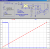
Since the LM358 comes two per package, I used the second one as a comparator to light a Red LED when the fuel level drops below about 2 gallons. Look at the plots. The Red trace is the voltage across the gauge as a function of the number of gallons (Xaxis). The Blue trace is the current through the LOW FUEL LED. I would use an ultra-bright Red LED for good daylight visibility.
This has been a fun project. I would appreciate some feedback on how it works out.
This site uses cookies to help personalise content, tailor your experience and to keep you logged in if you register.
By continuing to use this site, you are consenting to our use of cookies.