William At MyBlueRoom
New Member
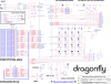
Here's the beta schematic for kit #2.
It's a companion PCB for the Inchworm ICD2.
It's got a 16x2 backlit LCD, 4x4 keypad, piezo speaker, IR input, POT, Switch, 4MHz & 350 Solderless Breadboard & 20pin expansion header.
It's targeted at simplicity and low cost yet useful. You should be able to build 100s of projects with it.
The 16F877A was chosen because it has the most free complier support.
4MHz was chosen as an introductory speed, nice 1us clock and is the default speed for a great deal of PIC software.
It's also somewhat small approx 4"x6" to fit into a Hammond sloped case.
")
